¶ INTRODUCTION
This guideline aims to help you out with all of the basic functions you need to know when you act as an air traffic controller on the network.
It is designed to ensure you get most of the tips so you will be experienced enough to deal with the software and make the best out of your first session.
¶ GENERAL IVAC WINDOWS LAYOUT
After launching IvAc, you will obtain a view like this:
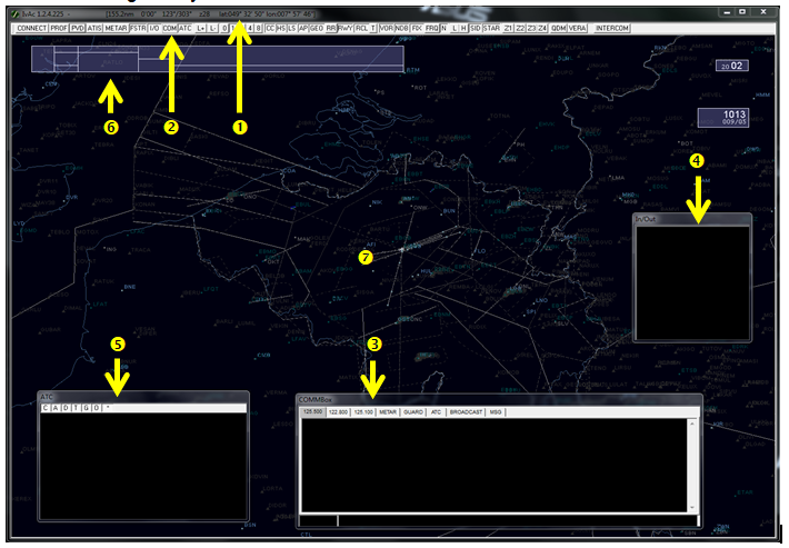
You can see the available zones:
- Windows bar information
- IvAc tool bar
- COMMBox window
- In/Out box window
- ATC box window
- Flight Strip
- Radar Screen (Primary View Display)
¶ WINDOWS BAR
This window presents:
- IvAc version (IvAc 1.2.4.225 in this example)
- Coordinates of the mouse cursor (where you point the mouse) in terms of longitude and latitude
¶ IVAC TOOL BAR
The ATC Tool bar is a set of shortcuts to several functions. In order to activate one of them, you simply have to click on it (if you need the ATC box, simply click on ATC). See the image below.

The functions are placed into several groups:
- CONNECT allows you to connect to or disconnect from the network. It opens a connection window
- PROF allows you to manage saved profiles for each position. It opens a profile window
- PVD allows you to set the configuration parameters of IvAc
- ATIS allows you to configure your active ATIS. It opens the ATIS window
- METAR allows you to set the ICAO airport code and get the active METAR of this position
- FSTR activates the display of the flight strip on screen which is the flight plan summary
- I/O activates the display of the inbound/outbound window
- COM activates the display of the communication window (COMMBox)
- ATC activates the display of the air traffic controllers and observers connected around your position
- Buttons for label position setting (L+/L-) will change the position of aircraft labels
- Speed vector settings (0,1,2,4,8) will select the speed vector length in minutes
- Airspace and Geo display buttons activate the display of the selected areas
- Range Rings and final axis display buttons activate the display of the selected functionalities
- Radio navigation display buttons activates the display of beacons and fixes on the radar screen
- Airways and SID/STAR display buttons activate the display of the airways and the preprogrammed SID and STAR on the radar screen
- Programmable zoom allows you to set your own radar zoom and use them with one click
- Advanced functions QDM, VERA, INTERCOM
¶ ATIS LETTER, QNH, UTC TIME BLOCK
The ATIS block is a good feature for any position. It shows the current ATIS in use represented by a letter from ‘A to Z’, the QNH and the wind speed and direction.

The time is represented in the UTC block.

¶ COMMBOX WINDOW
This is the text communication window. This is a mandatory window to be displayed.
It provides:
- Current active text frequency tab when you control a position (to receive text messages from pilots)
- Secondary text frequency tab in order to read out another position or UNICOM (optional)
- Third text frequency tab in order to read out another position or UNICOM (optional)
- METAR tab which displays programmable bank of METAR
- GUARD tab to be used for emergency purposes only (DANGER)
- ATC tab which can be used to communicate between all nearby ATC
- BROADCAST tab which is a “receive only” TAB. In this tab you will receive general information sent by Supervisor and/or Administrator
- MSG tab which receives the server information
- Call Sign zone where the traffic call sign is shown after selection by mouse click
- Scratch Pad zone where you type your message after tab selection
- Receive Zone where you receive the text communication or information in function of the tab selection.
There is also a Chat tab (not shown) created at the right of the MSG tab, named chat1, chat2, chat3…..
These chat TABs are created when you receive a private message or if you want to create this chat tab in order to send a private message to someone connected to the network (ATC, Pilot, Observer, Supervisor).
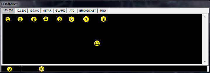
You will have to keep an eye on the COMMBox window from now on and then during the entire controlling session.
¶ FLIGHT STRIP
IvAc is able to show an extract of the flight plan of a selected aircraft in a flight strip format.

This flight strip shows various information:
- Destination airfield ICAO code (EBBR), Flight rules (I) and transponder code (1000)
- First cruise flight level or altitude (F360)
- Aircraft ICAO code (B773), its wake turbulence category (H) and its cruise true air speed (M083)
- First alternate airfield ICAO code (LFPG)
- Vocal pronunciation of airline prefix of the aircraft’s call sign
- Call sign
- Departure airfield ICAO code (LFBO) and estimated off-block time (UTC)(19H10) (also referred to as Departure time)
- Tags inserted by air traffic controllers for personal use or for coordination (120, KERKY)
- Route flown (FISTO…. ARVOL)
- Remarks zone filled by the pilot
The IVAO flight strip is the representation of a flight strip paper used in some air traffic control systems.
¶ INBOUND / OUTBOUND WINDOW (IN/OUT)
This window is a programmable window and shows inbound and/or outbound traffic from one or several airfields.
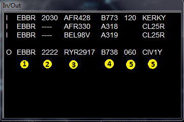
There are two groups of traffic:
- Arriving traffic on the selected airfield are tagged with an ‘I’ as inbound.
- Departing traffic on the selected airfield are tagged with an ‘O’ as outbound.
Each line is representing an aircraft with information displayed on this window:
- Selected Airfield
- Expected arrival or departure time
- Aircraft call sign
- Aircraft ICAO code
- Tags (FL and fix) inserted by air traffic controller
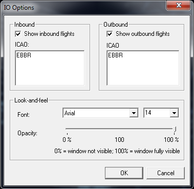
The option box allows you to select which airport you want to show.
You can just insert a list of ICAO airfield code you want to monitor. You can use partial ICAO code in order to use multiple selections. (ex LEM for all airfields starting with LEM like LEMD, LEMC…)
¶ ATC BOX
This window gives you a quick head up of the air traffic controllers, staff members, supervisors and observers connected all around your radar center position.
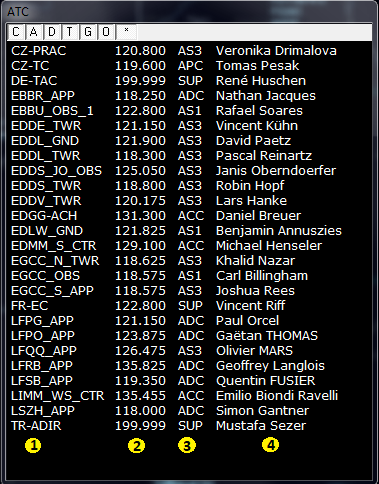
You can filter this information using the letter buttons located at the top line
- C as center,
- A as approach,
- D as delivery,
- T as tower,
- G as ground,
- O as observer,
- displays all positions.
If you want to display the approach position only, you just have to press ‘A’.
When no button is selected, only the programmed ICAO airfields in the ATC box option window are shown.
The data presented in this window are:
- User call sign (active air traffic controller, observer, staff member)
- VHF primary frequency (MHz)
- ATC, Supervisor or Administrator rank
- Full name of the connected user
¶ RADAR SCREEN
The radar screen is the main source of information for an active air traffic controller.
The radar screen contains:
- Representation of airspaces areas
- Navigation aids signs (VOR, NDB, DME…)
- Fixes signs
- Aircraft position labels and history dots
- Airfield final approach axes
- Airfield ground layout
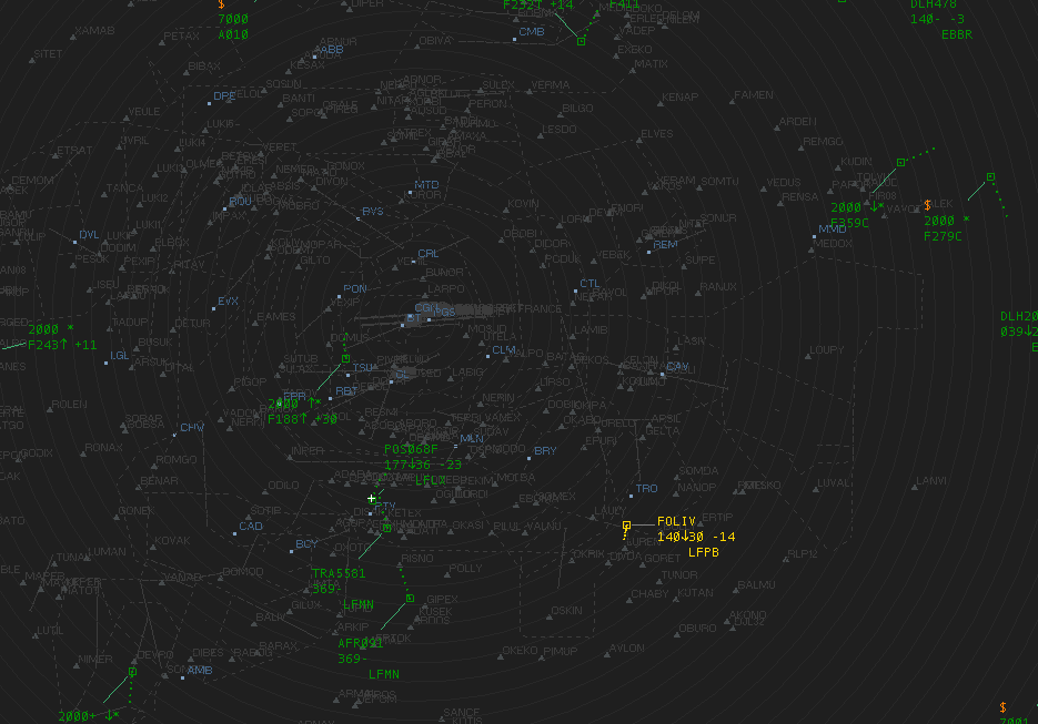
Representation of LFFF (Paris) area control position (large position with many areas and aircraft)
The colour is at your own discretion; you can define you own colour set or select predefined colours used in real radars.
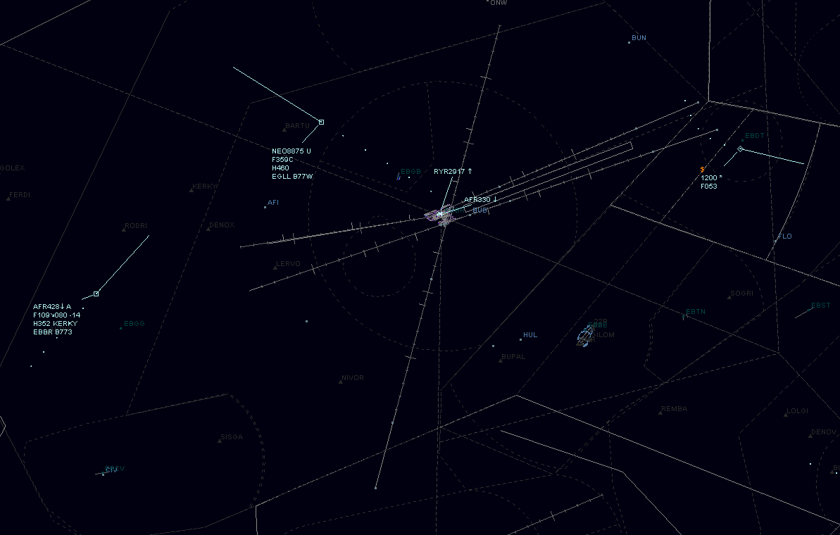
Representation of EBBR (Brussels) approach control position
¶ TRAFFIC REPRESENTATION
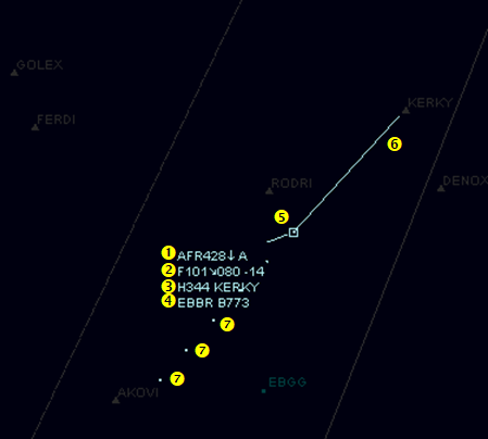
In the radar screen, you will normally have some aircraft flying. When assumed or in detailed observation mode, the traffic may look like the image below:
- Call sign of aircraft (AFR428), arrow which indicates that the aircraft is inbound or outbound of the airfield and the air traffic controller tag who assumes this traffic (A)
- Current altitude or flight level (F101), cleared flight level tag filled by air traffic controller (080) and vertical speed of the aircraft expressed in hundreds of feet (-14 as for -1400ft/min)
- Wake turbulence category (H), current ground speed in knots (344) and point cleared tag filled by air traffic controller
- Destination airfield (EBBR) and aircraft ICAO code (B773)
- Position of the aircraft ( dot in the middle of a square)
- Speed vector (selected from the tool bar)
- History dot (old position of the aircraft)
On the radar screen, you may find other representations
- Traffic flying non assumed in UNICOM (U) with no TAG
- Traffic flying with a 2000 transponder code and non-identified (*) only the altitude is shown
- Traffic on ground with a 7000 transponder code and non-identified (*)

¶ IVAC CONFIGURATION
One of the main advantages of the software is that you are free to configure IvAc at your own discretion.
It is important to know how to configure your IvAc. It might sound ‘boring’ to do but it will just enhance the simulation.
¶ CREATING AND LOADING CONFIGURATION
In order to access the configuration menu, simply click on PVD on the IvAc bar:
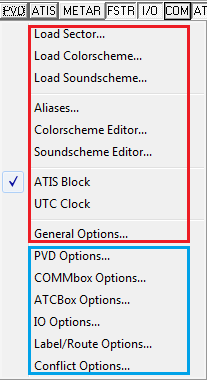
- Load Sector: it allows you to navigate through your sector file list and pick up the appropriate sector where you want to control or monitor.
- Load Colorscheme: it allows you to change the colour of your IvAc radar screen.
- Load Soundscheme: it allows you to change the sounds played by IvAc.
- Aliases: it allows you to build your own sentences of text command and instructions and link them to a shortcut to save time when controlling
- ATIS/UTC block: it displays the ATIS/UTC blocks on the radar screen.
- General options: it allows you to change the background color of the windows (I/O, COMMBox etc..) and proxy settings.
The other items options are defined in the chapters below. They are mainly windows configuration options.
¶ PVD OPTIONS
In the PVD Options window you can change the visibility range and hide (partially or completely) the representation of traffic on the radar screen by using the vertical altitude filters.

PVD option windows
In this window you can find:
- The visibility range filter. Click on the cursor and move it to the right or the left in order to increase or decrease your area of reception (outside this area you will not see any traffic). If you open a controlled position, we advise not to modify this value except in large areas of control (big CTR positions). If you increase the area of reception you will increase the IVAO server workload.
- The Primary Low altitude filter filters traffic representation data (including call sign) and shows only traffic with altitude above this selected level. (click on cursor and move it using the mouse in order to change the selected altitude)
- The Primary High altitude filter filters traffic representation data (including call sign) and shows only traffic altitude below this selected level. (click on cursor and move it using the mouse in order to change the selected altitude)
- Secondary Low altitude filter hides any traffic representation below this selected level. (click on cursor and move it using the mouse in order to change the selected altitude)
- Secondary High altitude filter hides any traffic representation above this selected level. (click on cursor and move it using the mouse in order to change the selected altitude)
The value of the secondary altitude filter may not be set below the primary filter’s one.
In case of an aircraft flying at a level above the level which you have set with your primary filter, it will be shown on your radar screen as follows:

¶ COMMBOX OPTIONS
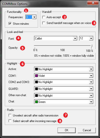
In the COMMBox options window you can change some parameters useful for text communication between yourself and the other users connected to the IVAO Network:
1. Functionality tab: it is possible to set the number of frequency tabs in your COMMbox (the first tab only is the active frequency). The Show minutes box gives for each text message the current minute of the current hour
2. Auto-accept option for automatic acceptation procedure of IvAc after a transfer of traffic
3. Send text transfer message to the traffic for acknowledgement of transfer
4. Font used in the COMMBox
5. Opacity of the COMMBox
6. Define tab activation colour after receiving a new message
7. Unselect aircraft after sending a text message
8. Automatic selection when receiving text message from an aircraft
¶ LABEL / ROUTE OPTIONS
This is the configuration of radar concerning the labels and the route options. We begin with the red numbers located on the left side of the window:
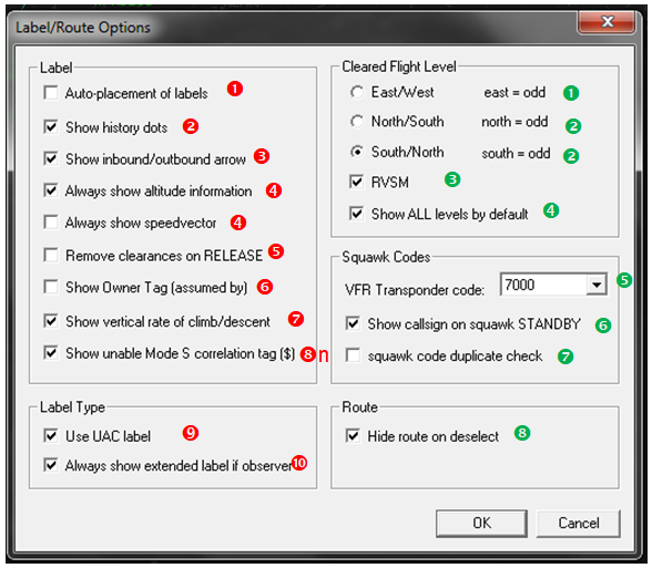
- Auto-placement of labels refers to the information above the dot. (You will not be able to change the position of the label if you tick this box)
- Show history dots which are the old position of aircraft showing its progress
- You may notice an arrow next to the call sign of an aircraft. It means the traffic is inbound your position (up arrow) or outbound (down arrow).
- According to the transponder equipment of each aircraft, you may have the possibility to read the altitude and sometimes not. The speed vector can always be hidden when selecting this option.
- Tick this box to remove completely the ATC label when you release an aircraft on UNICOM.
- This tag can display the ATC position who assumed this aircraft (A for approach, T for tower …)
- Display (or do not) the climb/descent rate in hundreds of feet
- When an aircraft does not have a S transponder, radar will add the $ sign next to the callsign
- Set different style of label (used for en-route position)
- Display all the label information like the air traffic controller has on his radar when connected as observer.
Now, we continue with the green numbers located on the right side of the window:
- When selected choose the East/West semi-circular rule level parity
- When selected choose the North/South semi-circular rule level parity
- When selected choose the availability of RVSM flight level in the selection between FL290 to FL410
- Cancel all previous selections and show all levels available in the cleared flight level label
- Set default non-controlled VFR transponder code
- Show at the minimum the call sign if the aircraft is on standby mode
- Activate the duplicate check to enable conflict when using the same squawk number code for 2 or more different aircraft
- When you deselect an aircraft, if you were displaying the route, this will be hidden
¶ CONFLICT OPTIONS
Move down the cursor to select the appropriate alert options. Should the separation between two aircraft be below the settings, then they will be displayed on your radar screen in red, meaning you should concentrate all of your efforts to fix up the conflict matter.
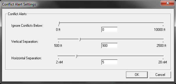
We advise you to use the following parameters:
- Ignore Conflicts Below : choose a value between 1500ft and 1900ft, this value shall be above traffic aerodrome pattern altitude +500ft in order not to take the aerodrome circuit in the conflict setting
- Vertical Separation: choose 900ft. If the minimum is 1000ft with the simulator precision and 100ft IFR tolerance, the minimum shall be 1000-100 = 900ft
- Horizontal Separation: choose typical 5NM default lateral IFR separation. It can be 3NM in some approaches in reduced minimum separation rules.
¶ FIRST CONNECTION
¶ CONNECTION TO THE NETWORK
The first thing you need to do is to fill in the connect page with your details and press connect.
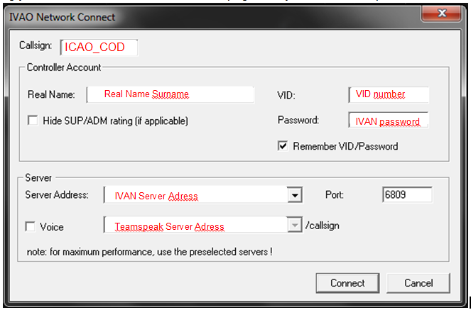
Check the MSG tab of your COMMBox to ensure you are connected.

At this stage, insert the right frequency of the position in your COMMBox with “// 134.925’”. Click on ATIS on the IvAc bar and fill it in carefully.
¶ PREPARE YOUR ATIS
Fill your ATIS information. Press ATIS button and fill it.

Please consult the documentation on how to fill the ATIS in the available documentation in IVAO.
¶ INTERACTION WITH AIRCRAFT
If you notice that there are aircraft in your zone and non-controlled by another controller, then right click on each aircraft in this case and press ASSUME.
If you notice that there are aircraft in your zone and controlled by another controller, please coordinate the transfer of that aircraft with the adjacent controllers and await the aircraft call.
With assuming each aircraft on your control, you will know:
- You have the hand on it and the label colour of the assumed aircraft will also change
Only assume them if you are sure they are in your area of control.
¶ IMPORTANT FUNCTIONS
When you right click on assumed traffic, you will obtain this menu:
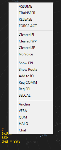
- ASSUME: in order to select the traffic to be your property in your area of control
- TRANSFER : in order to send the traffic to another controller, you must select the right controller in the list shown after the left click
- The RELEASE function has to be used whenever you send the traffic to UNICOM
- FORCE ACT has to be used with extreme precaution. It sends a text message and makes a loud sound to the pilot, stating he has to contact you
- Cleared FL: setup the flight level tag on assumed traffic
- Cleared WP: setup the waypoint tag on assumed traffic
- Cleared SP: setup the speed tag on assumed traffic
- No Voice: set or unset the no voice tag
- Show FPL: show ICAO flight plan
- Show Route: show route of the traffic
- Add to IO: Add this traffic to the IO window
- Req COMM: Request the active communication of the traffic
- Req FPL: Request flight plan of the traffic
- SELCAL: advanced function for oceanic control
- Anchor: set Anchor on screen
- VERA: activate the analysis tool for conflicting traffic
- QDM : activate bearing indication
- HALO : activate fictive proximity circles
- Chat: initiate chat by text
¶ SEE ALSO
- None
¶ REFERENCE
- None
¶ AUTHOR
- VID 150259 - Creation
- VID 256272 - Wiki Integration
- VID 346148 - Wiki Migration
¶ COPYRIGHT
- This documentation is copyrighted as part of the intellectual property of the International Virtual Aviation Organisation.
¶ DISCLAIMER
- The content of this documentation is intended for aviation simulation only and must not be used for real aviation operations.