¶ London Terminal Control Operations Manual
London Terminal Control (LTC) in the real world is located at the London Terminal Control Centre (LTCC) which is also co-located with the London Area Control Centre (LACC) at NATS Swanwick.
¶ Sectors
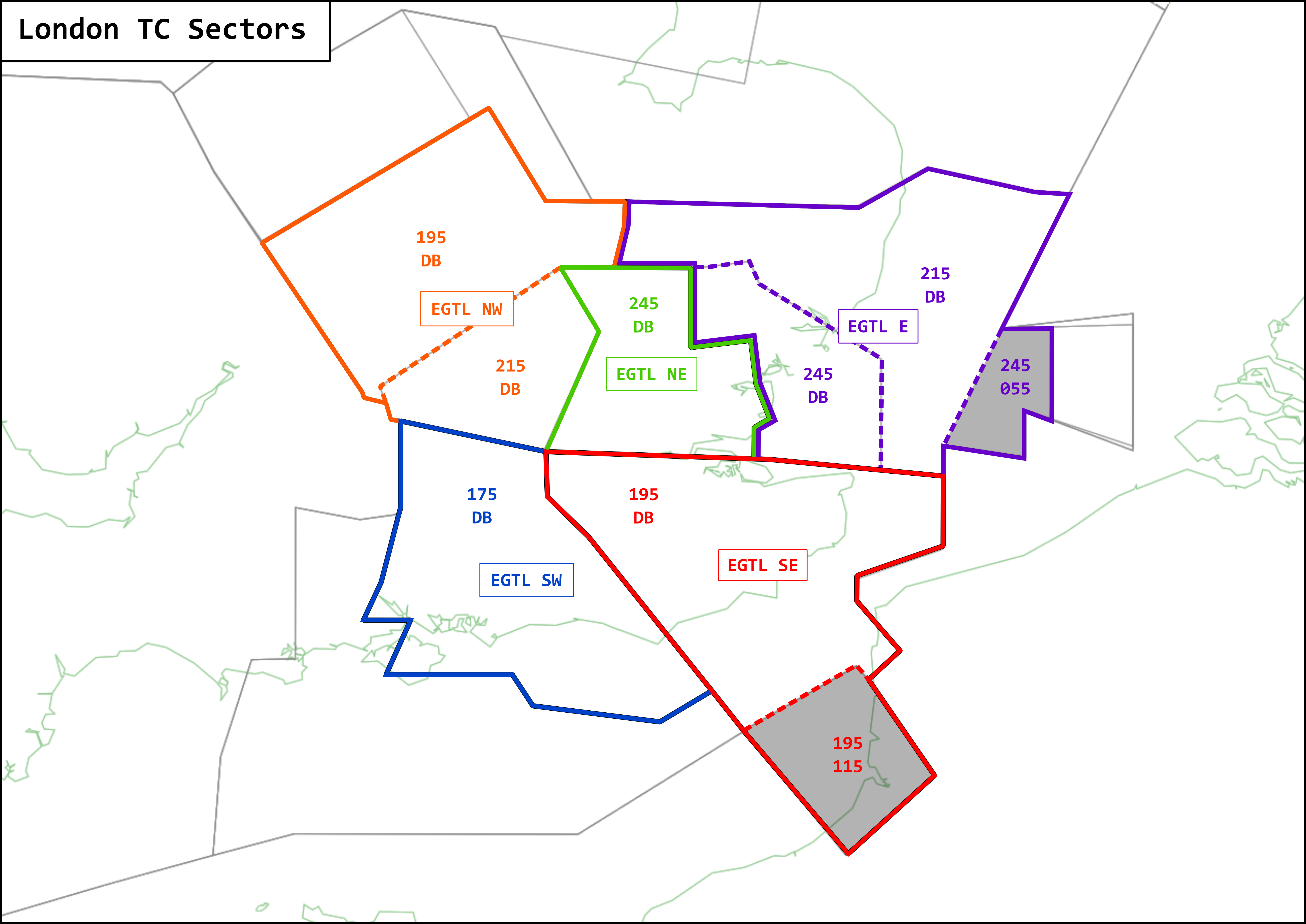
LTC can be split into five sectors, TC NE, TC NW, TC SE, TC SW and TC East. The vertical and lateral limits of these sectors are depicted in the diagram below.

¶ Sectorisation
| Sector ID | IVAN Callsign | RT Callsign | Channel | CPDLC Code | FRA |
|---|---|---|---|---|---|
| TC ALL | EGTL_CTR | London Control | 124.930 | not used | APC+ |
| TC NTH (Bandbox) | EGTL_N_CTR | London Control | 121.280 | not used | APC+ |
| TC STH (Bandbox) | EGTL_S_CTR | London Control | 135.805 | not used | APC+ |
| TC NE | EGTL_NE_CTR | London Control | 118.825 | not used | APC+ |
| TC NW | EGTL_NW_CTR | London Control | 119.780 | not used | APC+ |
| TC SE | EGTL_SE_CTR | London Control | 120.530 | not used | APC+ |
| TC SW | EGTL_SW_CTR | London Control | 134.125 | not used | APC+ |
| TC East | EGTL_E_CTR | London Control | 129.605 | not used | APC+ |
¶ Event Sectors
| Sector ID | IVAN Callsign | RT Callsign | Channel | CPDLC Code | FRA |
|---|---|---|---|---|---|
| TC LOGAN | EGTL LOG CTR | London Control | 135.425 | not used | APC+ |
| TC LAM | EGTL LAM CTR | London Control | 123.900 | not used | APC+ |
¶ Policy
LTC ALL, NTH or STH may be opened at any time, before finally splitting in to each of the five (NE, NW, SE, SW, East) sectors.
¶ Bandboxing
| Bandbox | Sector Split 1 | Sector Split 2 |
|---|---|---|
| TC ALL | TC North | TC NE |
| TC NW | ||
| TC East | ||
| TC South | TC SE | |
| TC SW |
Should ALL be online in conjunction with any other LTC sector, ALL should relinquish control of the relevant sector respectively.
¶ Top-Down Coverage
Controllers shall provide Approach and Aerodrome Control to the airfields listed below when the appropriate positions are not online.
Should two overlapping sectors be online at the same time, the lower of the two sectors shall be responsible for provision of Approach and Aerodrome control at the airfields listed below.
A service may be provided to aircraft at airfields not listed below within the lateral confines of a sector. Non-radar units must only be controlled at Approach level only (i.e. APP).
| Sector ID | Aerodromes Controlled |
|---|---|
| NE DEPS | EGLC, EGMC, EGSS |
| NW DEPS | EGBB, EGGW |
| SE DEPS | EGLL |
| SW DEPS | EGKK, EGHI, EGHH |
| East | Nil |
¶ Suspension of Top-Down Coverage
When high levels of traffic are forecast in a sector (for example during an event). LTC controllers may suspend the top down control at airfields under their responsibility. In such cases, the lowest flight level at which a service can be provided must be notified by ATIS.
¶ Separation Standards
¶ Vertical Separation
Vertical separation exists when the vertical distance between aircraft is never less than the prescribed minimum. The vertical separation minima are:
Between aircraft flying subsonic:
- Up to FL290 apply 1,000 ft
- Above FL290 apply 2,000 ft, except that between FL290 and FL410 inclusive, 1,000 ft may be applied between RVSM approved aircraft operating in airspace designated as being notified for the application of this separation standard
Between aircraft flying supersonic and between aircraft flying supersonic and aircraft flying subsonic:
- Up to FL450 apply 2,000 ft
- Above FL450 apply 4,000 ft
¶ Horizontal Separation
¶ Radar Separation Minima
Minimum radar separation to be applied is 5nm, or 3nm/2.5nm where approved.
¶ Use of 3nm Separation
The use of 3nm separation is approved for the following positions. Provided that aircraft are identified displaying a validated SSR code, within controlled airspace and the sectors area of responsibility:
- All LTC sectors
The use of 3nm separation shall be increased to 5nm prior to the transfer of control of aircraft entering airspace not approved for 3nm separation.
¶ Ensuring Horizontal Separation
Aircraft on their own navigation where horizontal separation is expected to be less than 15nm and no vertical separation exists should be given radar headings to ensure separation.
¶ RVSM Procedures
Reduced Vertical Separation Minimum (RVSM) permits the application of a 1000ft vertical separation minimum (VSM) between suitably equipped aircraft in the level band FL290-FL410 inclusive, thereby making available six additional usable flight levels.
| Track from 180 to 359 (Westbound) | Track from 000 to 179 (Eastbound) |
|---|---|
| FL430 | FL410 |
| FL400 | FL390 |
| FL380 | FL370 |
| FL360 | FL350 |
| FL340 | FL330 |
| FL320 | FL310 |
| FL300 | FL290 |
| FL280 |
The vertical limits of the RVSM airspace are FL290 up to and inclusive FL410.
Note: FL280 is the next usable FL below RVSM airspace. FL430 is the next usable FL above RVSM airspace (2000ft separation).
¶ Altimeter Setting Procedures
¶ Transition Level & Minimum Stack Level
| Transition Altitude | ||||||
|---|---|---|---|---|---|---|
| 3000ft | 5000ft | 6000ft | ||||
| QNH | TL | MSL | TL | MSL | TL | MSL |
| 1060-1050 | 30 | 40 | 50 | 60 | 60 | 70 |
| 1049-1032 | 35 | 40 | 55 | 60 | 65 | 70 |
| 1031-1013 | 40 | 40 | 60 | 60 | 70 | 70 |
| 1012-995 | 45 | 50 | 65 | 70 | 75 | 80 |
| 994-977 | 50 | 50 | 70 | 70 | 80 | 80 |
¶ Transfer of Control & Communications
Aircraft under the control of one sector are not permitted to penetrate the airspace of another sector unless:
- The aircraft is following a standing agreement; or
- Assumed Coordination is in effect; or
- Prior coordination has taken place
¶ Standing Agreement
Aircraft may enter the airspace of another sector without the need for individual coordination provided that:
- It is following a standard route on its own navigation, or on a specified track on a heading; and
- It has been cleared to or is at the standing agreement level before transfer of communication
Unless specified within the standing agreement, transfer of control will occur at the same time as transfer of communications provided that:
- The receiving sector continues the flight in the same general direction and does not reverse the vertical profile (e.g. climb a descending aircraft) or stop at an intermediate level within the confines of the offering sector
- Any potential conflicts with aircraft in the offering sectors airspace are resolved prior to transfer of communications
Unless the standing agreement states otherwise:
- Aircraft may be released for climb or descent within the confines of the offering sector
- Aircraft may be released for turns on own navigation such that the flight path is altered by not more than 45° left or right within the confines of the offering sector
- Aircraft transferred on a heading must be coordinated prior to issuing a heading change within the confines of the offering sector.
¶ Assumed Coordination
A sector may transfer traffic that is not covered by a standing agreement without coordination provided that:
- The aircraft is in the cruise at the RFL
- The aircraft is following the planned route, or on a heading within the confines of that route
- The aircraft is not an Opposite Direction Level
¶ Delegated areas of ATS
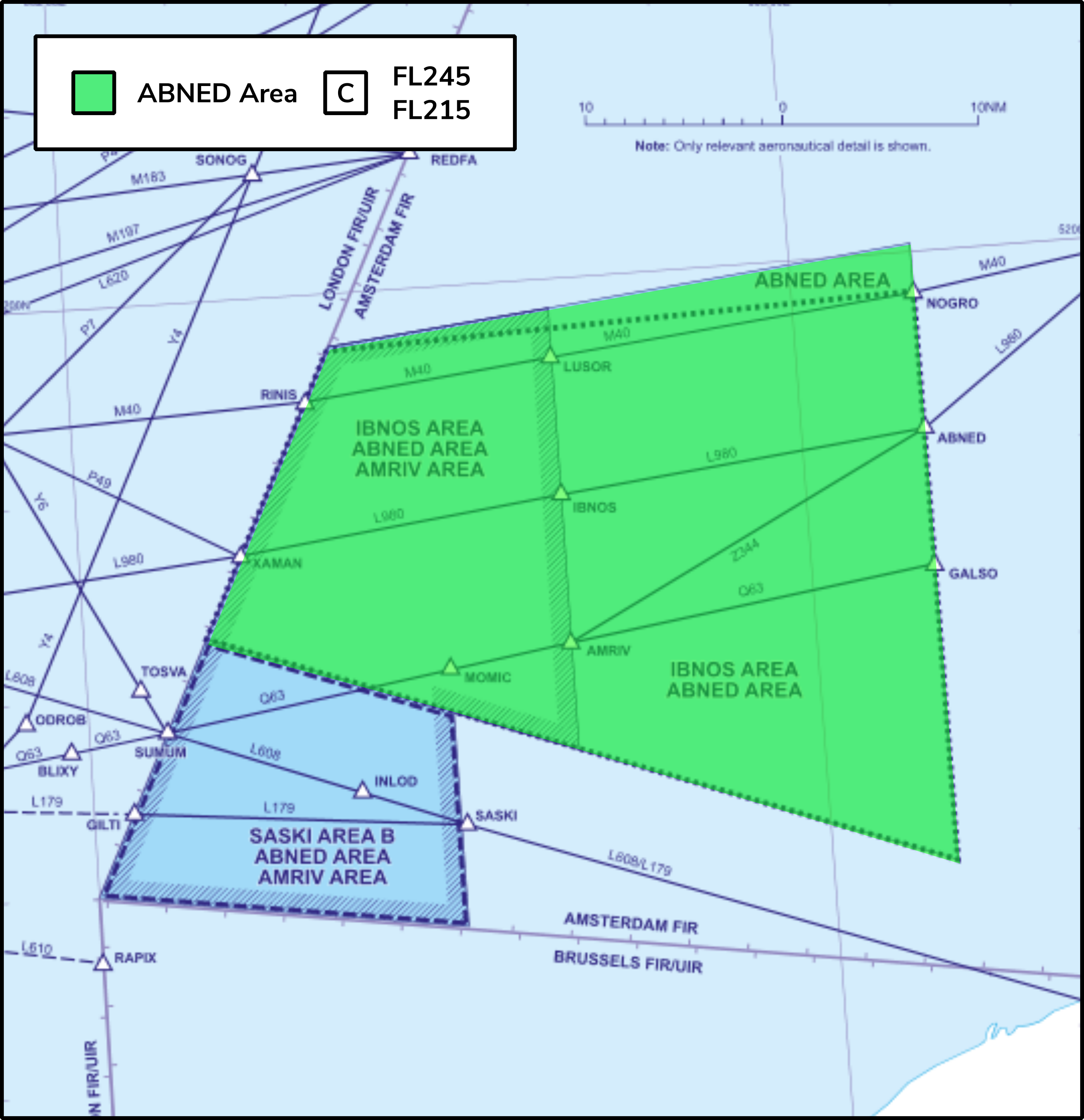
ABNED Area

Backround chart - NATS UK AIP ENR 6-47
FL 215 - FL 245— Class C Airspace (ATS - London Terminal Control (Swanwick)).
In these parts of the Amsterdam FIR the United Kingdom will provide Air Traffic Services to all aircraft between FL 215 and FL 245 (inclusive). Procedures and communications will be as if this airspace was an integral part of the London FIR/UIR. This area is bounded in succession by the following points:
AMRIV Area

Backround chart - NATS UK AIP ENR 6-47
FL 195 - FL 215 — Class C Airspace (ATS - London Terminal Control (Swanwick)).
FL 55 - FL 195 — Class A Airspace (ATS - London Terminal Control (Swanwick)).
In these parts of the Amsterdam FIR the United Kingdom will provide Air Traffic Services to all aircraft between FL 55 and FL 215 (inclusive). Procedures and communications will be as if this airspace was an integral part of the London FIR/UIR. This area is bounded in succession by the following points:
Lille TMA

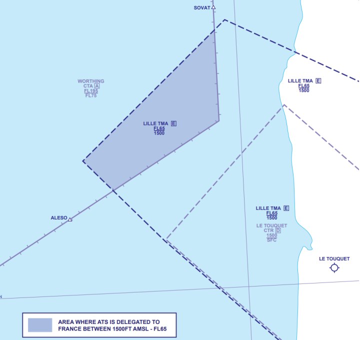
Diagram - EGTT-LFFF LoA
Part of Lille TMA Area 7 - 1500 FT AMSL - FL 65 Class E Airspace (ATS Lille Approach).
In this part of the London FIR, France will provide Air Traffic Services to all aircraft between 1500 FT AMSL – FL 65 (inclusive). Procedures and communications will be as if this airspace was an integral part of the Paris FIR.
La Manche East

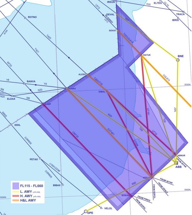
Diagram - EGTT-LFFF LoA
La Manche East (Low) – FL 115 - FL 265.
FL 115 - FL 195 — Class D Airspace (ATS - London Terminal Control (Swanwick)).
FL 195 - FL 265 — Class C Airspace (ATS - London Area Control (Swanwick)).
In these parts of the Paris FIR the United Kingdom will provide Air Traffic Services to all aircraft between FL 115 and FL 265 (inclusive). Procedures and communications will be as if this airspace was an integral part of the London FIR/UIR.