¶ Introduction
A Non Directional Beacon (NDB) is a radio station placed at an identified location and it is used as an aviation or maritime navigation aid. In aviation, the NDB use is regulated by the annex 10 of ICAO which specifies that NDBs are exploited over a frequency range between 190 and 1750 kHz (in Europe this range is reduced within 255 and 525 kHz).
These beacons are mostly located near airports since they provide the simplest navigation information to reach an airport. A NDB is characterized by its range:
- Long range (100 NM): it is used as a reference point for en route navigation but also as a holding fix or an initial approach fix (IAF) near airports.
- Small range (25 NM): it is essentially used as a holding or initial approach fix near airports. In some countries, when NDBs are used as IAF, they are often called locators.
The signals from a NDB are received by an instrument in the airplane called ADF (Automatic Direction Finder).
Read more about the Non-directional beacon - NDB (Beacon)
¶ On-board equipment: ADF
The Automatic Direction Finder -- ADF - when tuned to a selected NDB frequency, is the on-board equipment that determines the relative bearing (RB) from the aircraft to the ground beacon or station.
The relative bearing (RB) is the number of degrees measured clockwise between the heading of the aircraft and the direction from which the bearing is taken. The relative bearing must be corrected with the aircraft position's variation and heading to obtain the magnetic bearing (MB) (the variation is the difference between the true north and the magnetic north).
Typical ADF equipment includes:
- 2 antennas:
- Sense aerial: is the non-directional antenna that receives signals from all directions.
- Loop aerial: is the rotating antenna that best receives signals from only two directions.
- Receiver: the control unit, usually found next to radio panels.
- Indicator instrument: the instrument where the information is presented to pilots. It does not normally have any form of failure warning system such as a flag, so great care must be taken.
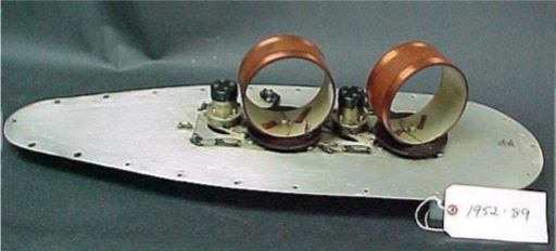
The NDB transmits signals in all directions that reach airborne ADF's loop and sense antennas. When both inputs are processed together, the equipment is able to display the relative bearing on the indicator instrument.
¶ Frequency selector
The ADF receiver is the control unit where pilots select NDB frequencies from which they want to obtain the bearing.
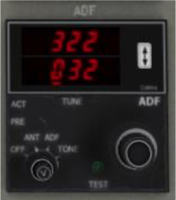
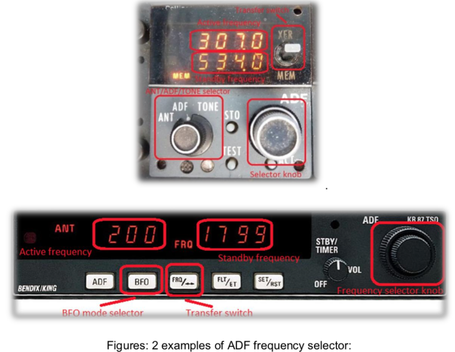
ADF equipment has its own controls:
- Frequency selector: used to select the NDB frequency. It can be digital or analogue, depending on the equipment. Frequencies are tuned by rotating a knob until the wanted frequency is obtained.
- BFO (Best Frequency Oscillator): it must be turned on when identifying a non A1A beacon, so that the aural identification can be heard.
- Antenna mode:
- ANT: only sense aerial will work.
- NDB/ADF: both sense and loop aerials will work. This mode is the most advisable.
- LOOP: only loop aerial will work. It usually is linked to another switch called 'Loop L/R' which with the aerial can be rotated left or right.
Depending on the equipment, there could also be two displays showing the ACTIVE and STANDBY ('SBY') frequencies. In this type of control units, the frequency is first selected on the STANDBY frequency display and then transferred to the ACTIVE frequency using the transfer switch (XFR) located normally between the displays.
¶ Indicator instruments
Relative bearing from NDBs can be shown in two different instruments:
- Radio Bearing Indicator (RBI)
- Radio Magnetic Indicator (RMI)
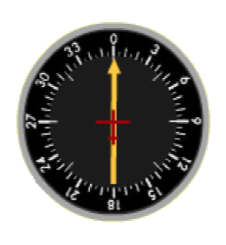
Basic instruments consist of a compass rose with one needle that may indicate Relative Bearing (RB) or Magnetic Bearing (MB), depending on the instrument. The head of the needle indicates bearing TO the station and the tail of the needle indicates bearing FROM the station.
¶ Radio bearing indicator with fixed card
It only has one needle and a fixed (not movable) compass rose. It always indicates heading North at the top of the instrument.
The moving needle indicates the Relative Bearing (RB) to the station, relative to the longitudinal axis of the aircraft (fore and aft axis). That Relative Bearing (RB) is read clockwise from 0o until the value the needle is pointing at.
This is the simplest instrument and so its usage is not easy since the Magnetic Bearing (MB) is not shown at first glance. Relating to the current heading, the pilot will need to check the relative bearing and calculate the Magnetic Bearing (MB) each time.
Magnetic Bearing (MB) = Relative Bearing (RB) + aircraft heading.
¶ Radio bearing indicator with movable card
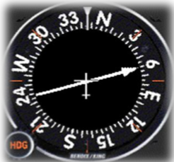
Similar to the radio bearing indicator with fixed card, this instrument has the advantage to have a compass rose which can be rotated manually by the pilot.
So the aircraft's current heading can be set on the top. This allows the instrument to show directly the Magnetic Bearing (MB), which eases the pilot's work.
In the figure, the movable card was put at a heading 345°. As a consequence the NDB magnetic heading is 060°.
¶ Radio magnetic indicator (automatic)
This is an advanced instrument as it automatically rotates the compass rose to represent the current aircraft heading at the top. The Magnetic Bearing (MB) can be obtained easily.
The RMI has one or two needles which can be used to indicate navigation information from either the ADF or the VOR receivers. Both needles are different in appearance, one of them operating with NAV 1 or ADF 1 radio and the other one operating with NAV 2 or ADF 2 radio.
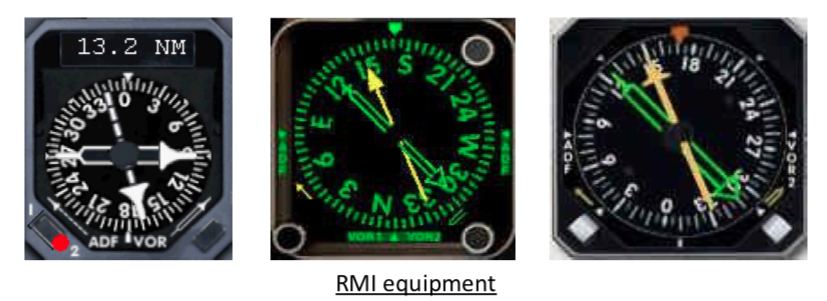
There are two switches that allow the pilot to change each needle source from VOR to ADF or from ADF to VOR.
¶ Electronic horizontal situation indicator EHSI
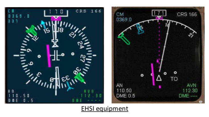
In more complex instruments mounted on bigger or commercial airplanes, the ADF might be integrated into glass cockpits EHSI where NDB bearings may be shown in the Navigation Display.
¶ Relative position between aircraft and NDB
The head of the needle indicates bearing TO the station and the tail of the needle indicates bearing FROM the station. The needle is not in function of aircraft heading.
¶ Inbound NDB
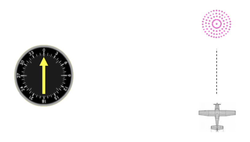
The needle on the ADF is pointing north. Then the NDB is in front of the aircraft.
¶ Outbound NDB
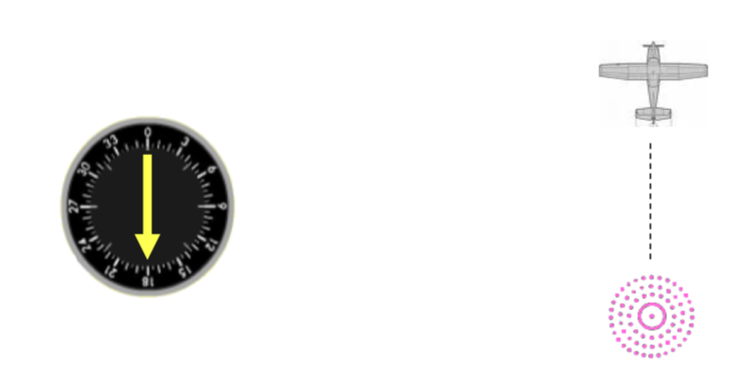
The needle on the ADF is pointing south. Then the NDB is behind the aircraft.
¶ Lateral NDB
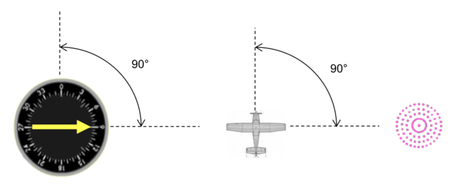
The needle on the ADF is pointing 90°. Then the NDB is on the right of the aircraft.
¶ 45° track
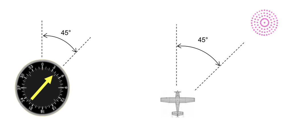
The needle on the ADF is pointing 45°. Then the NDB is on the right of the aircraft.
¶ Wind effect
When following a NDB navigation aid with presence of cross wind, if you maintain only the ADF at the top position of the instrument, your heading will increase or decrease like the image below.
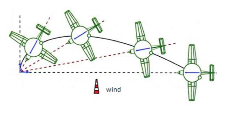
In this case, you do not make a direct and follow the same NDB track.
- None
- VID 150259 - Creation
- VID 450012 - Update
- VID 496402 - Wiki.js integration