¶ Introduction
In aerodynamics, the flight envelope defines operational limits for an aircraft with respect to maximum speed and load factor, given at a particular atmospheric density.
The flight envelope is the region within which an aircraft can operate safely.
If an aircraft flies 'outside the envelope' it may suffer damage; the limits should therefore never be exceeded
To calculate those limits we use te "V-n diagram
¶ V-n Diagram

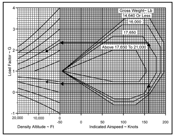
The picture above represents V-n diagram
The V-n diagram is a graph that summarizes an aircraft's structural and aerodynamic limitations at a particular weight, altitude and configuration.
- The horizontal axis is indicated airspeed.
- The vertical axis of the graph is load factor, or G's.
V-n diagrams define the maneuvering envelope of an aircraft
¶ Max Speed
The vertical line on the right side is called the redline airspeed, or VNE (Velocity never-to-exceed).
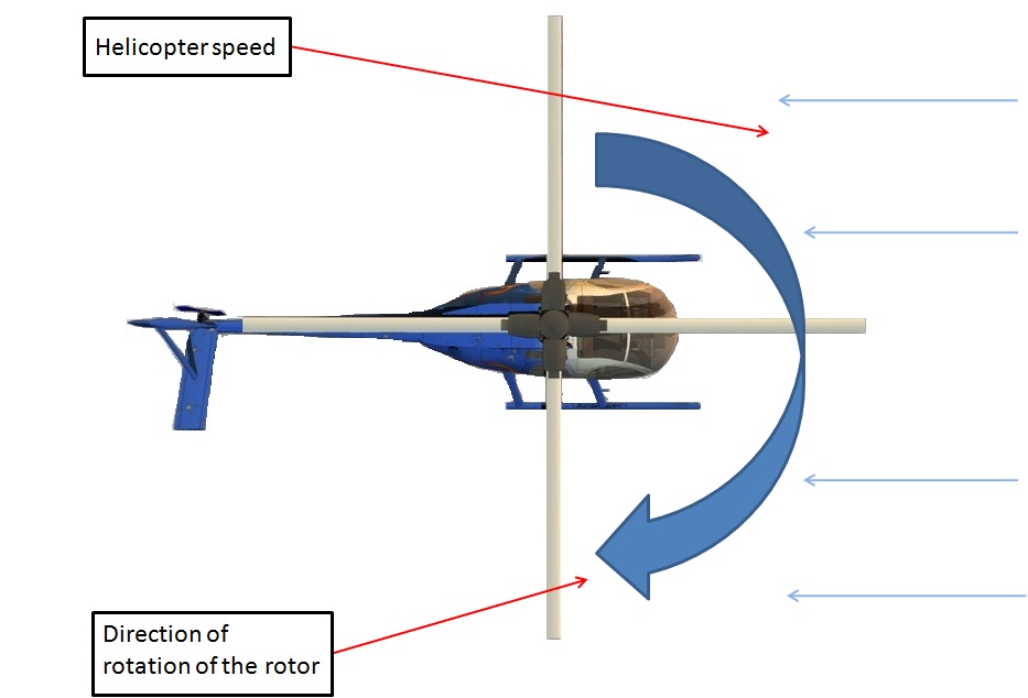
Redline airspeed is the highest airspeed that an aircraft is allowed to fly and it is determined by the rotor turning speed. If the rotor turning speed plus the helicopter speed is over Mach 1.0, it will cause a blade stall.
If maximum speed (VNE) is exceeded;
- Main rotor blades stalls and helicopter loses lift,
- Stalling main rotor blades creates excessive vibrations,
- Helicopter might suffer from structural damage.

In forward flight, the tip of advancing balde will have the highest speed. If forward speed exeeds maximum speed, it will reach M1.0 and start a stalling.
¶ Load Factor
The top and bottom of the V-n diagram are established by the structural limit line, or limit load factor.
Limit load factor is the greatest load factor an aircraft can sustain without any risk of permanent deformation.
It is the maximum load factor anticipated in normal daily operations. Aircraft will have both positive and negative limit load factors.
If the limit load factor is exceeded, some structural damage or permanent deformation may occur.
¶ Ultimate Load Factor
Ultimate load factor is the maximum load factor that the aircraft can withstand without structural failure.
There will be some permanent deformation at the ultimate load factor, but no actual failure of the major load-carrying components should occur.
If you exceed the ultimate load factor, structural failure is imminent.
¶ Lift Limit
The left-hand side of the V-n diagram is the lift limit. This is the maximum load factor available at a given airspeed.
An aerodynamic limit of rotor thrust exists at speeds less than maneuver speed because air mass flow through the rotor is decreasing and the rotor can't generate high transient thrust levels.
Attempted hard aft cyclic maneuvering at low speeds will result in further reduced speed and "g available".
Many helicopters have the capability of generating in excess of four transient 'G's at high speed. It is unusual for a helicopter to be able to sustain more than two 'G's.
- None
- Naval air training comand CNATRA P-401 (Rev. 10-09)
- VID 241036 - Creation
- VID 497664 & 496402 - Wiki.js integration