¶ Introduction
The HSI is an aircraft instrument normally mounted in place of a conventional heading indicator. It combines a heading indicator with a VOR/ILS display.
On the HSI, the aircraft is represented by a schematic figure in the centre of the instrument – the VOR/ILS display is shown in relation to this figure. The heading indicator is usually slaved to a remote compass and the HSI is frequently interconnected with an autopilot capable of following the heading select bug.
In this instrument, there are:
0) Course deviation bar (yellow)
1) TO/FROM indicator
2) Course select knob
3) Course deviation scale
4) Compass card (automatic rotation for HSI with heading)
5) Select course pointer (only for HSI)
6) Symbolic aircraft (only for HSI)
7) Heading select knob (only for HSI)
8) Heading select bug (only for HSI)
9) NAV (or GS) flag warning
10) Lubber line (orange or white)
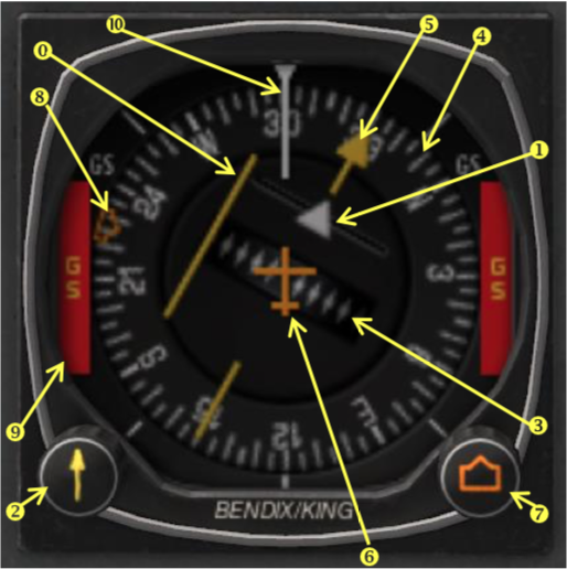
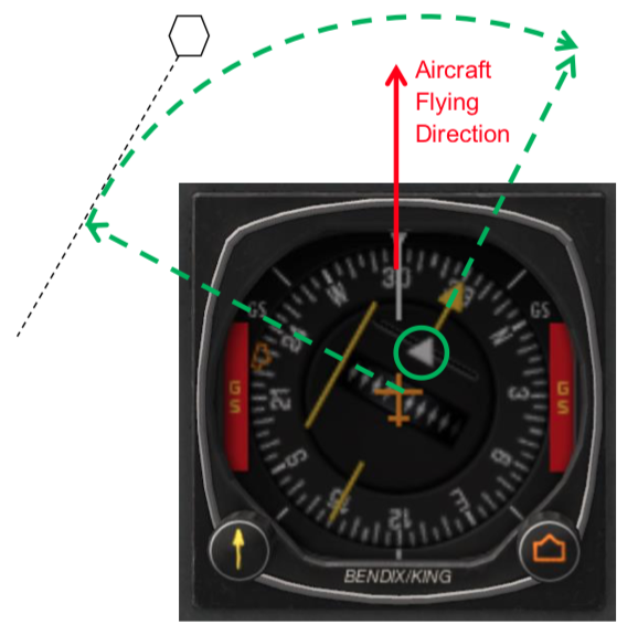
Lubber line represents the current aircraft flying direction.
The HSI illustrated above is a type designed for smaller airplanes and is the size of a standard 3 1⁄4 inch instrument. Airline and jet aircraft HSIs are larger and may include more display elements.
The desired course is selected by rotating the course select knob in relation to the compass card. The HSI has a fixed aircraft symbol and the course deviation bar displays the aircraft’s position relative to the selected course.
The TO/FROM indicator is a triangular pointer:
- When the indicator points to the head of the course select pointer, the arrow shows the course selected. If properly intercepted and flown, the course will take the aircraft to the chosen facility.
- When the indicator points to the tail of the course select pointer, the arrow shows that the course selected, if properly intercepted and flown, will take the aircraft directly away from the chosen facility.
On a conventional VOR indicator, left/right and to/from must be interpreted in the context of the selected course.
When an HSI is tuned to a VOR station,
- Left and right always mean left and right
- TO/FROM is indicated by a simple triangular arrowhead pointing to the VOR. If the arrowhead points to the same side as the course selector arrow, it means TO, and if it points backwards to the side opposite the course selector, it means FROM.
¶ Electronic HSI
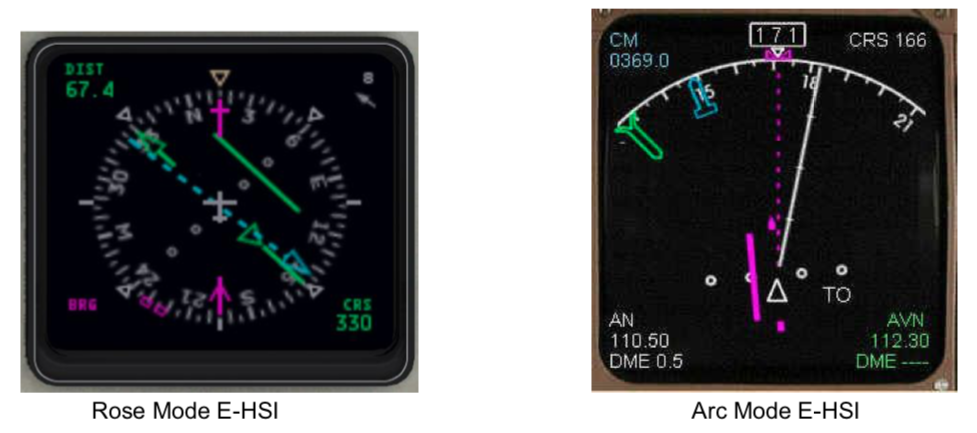
The most modern HSI displays are computerized and integrated with electronic flight instrument systems into dedicated instruments or into "glass cockpit" systems.
¶ HSI instrument reading
The HSI instrument is much easier to understand than the CDI instrument as there is no confusion with the current heading as the heading is displayed on the HSI.
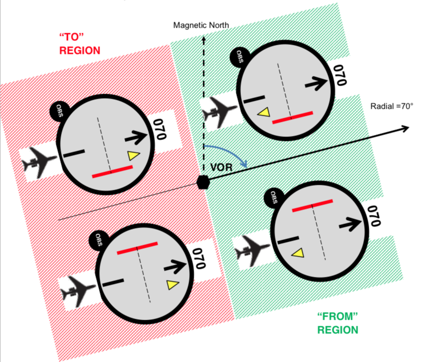
The definition of the TO/FROM region is the same as for the CDI.
When aircraft heading is the course, the HSI will have the same behavior as the CDI.
The main difference is that the HSI instrument will display the aircraft heading on top of the instrument and the course pointer will rotate in function of the aircraft turn.
Examples:
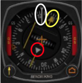
On the first HSI instrument, we can detect:
- White lubber line indicates the heading = 125°
- Yellow course pointer indicates the selected radial = 150°
- White triangle indicates the TO/FROM region = FROM
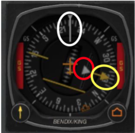
On the second HSI instrument, we can detect:
- White lubber line indicates the heading = 222°
- Yellow course pointer indicates the selected radial = 330°
- White triangle indicates the TO/FROM region = TO
¶ When heading equals course on the HSI
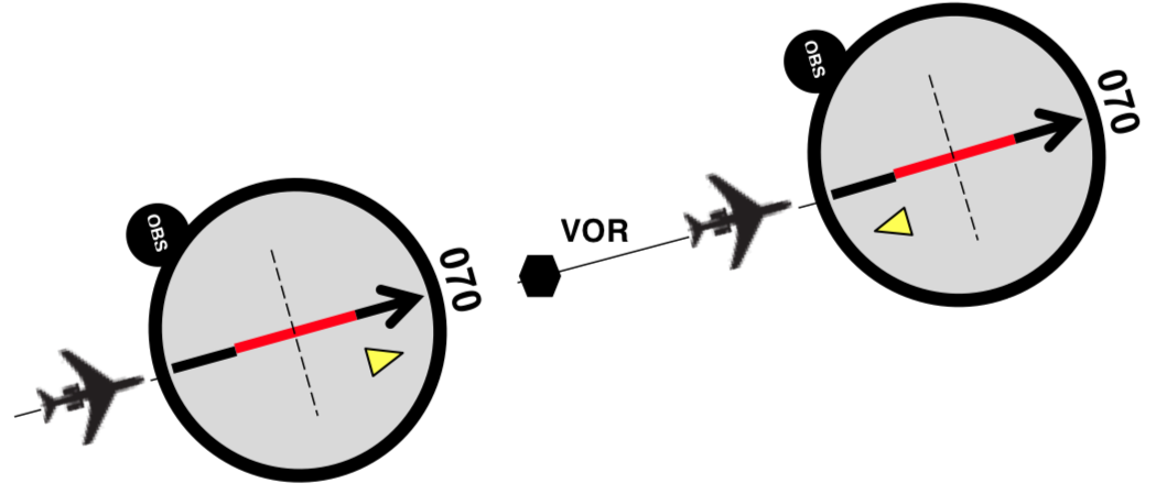
If the aircraft is exactly on the radial, the course deviation bar should be centered on the instrument.
¶ Heading does not necessarily equal course
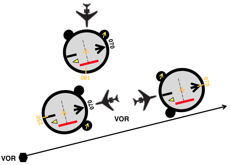
In the HSI instrument, the TO/FROM indicator (yellow triangle) always points toward the VOR direction. The course radial indicator (black arrow) represents the radial direction from the VOR. The course deviation bar (red) is located exactly in function of the aircraft heading. No confusion about aircraft heading and the course radial indicator rotates inside the instrument in function of the current aircraft heading (orange orientation values on the picture).
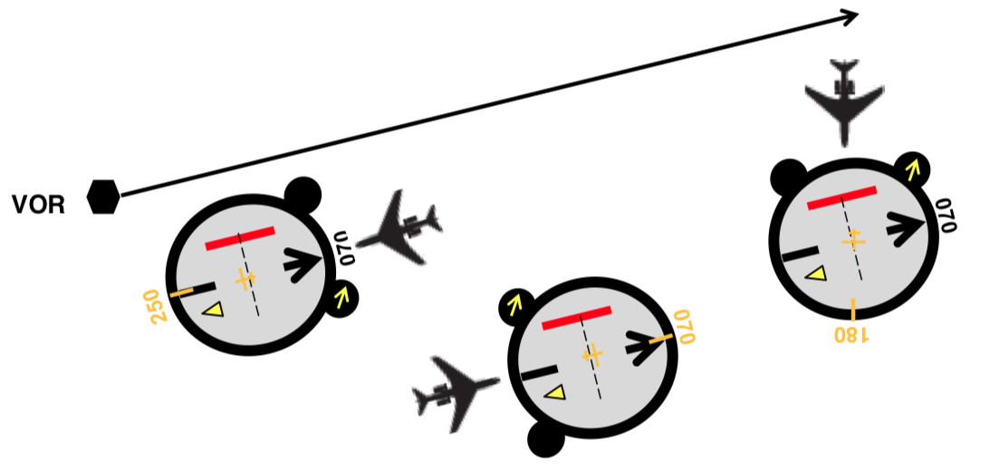
Another example above, in the other FROM quadrant.
¶ Where is the VOR and shortest distance to join the radial?
Using a CDI or a HSI, you must know as a pilot where the VOR is and which is the shortest path to reach it.
The VOR station is located in the sector determined by the TO/FROM flag in the direction of the radial and the shortest path in direction to the radial.
The shortest path can be determined by the direction from the centre of the instrument towards the course deviation bar. On the CDI instrument just read the number displayed on the compass card (±90° of the radial).
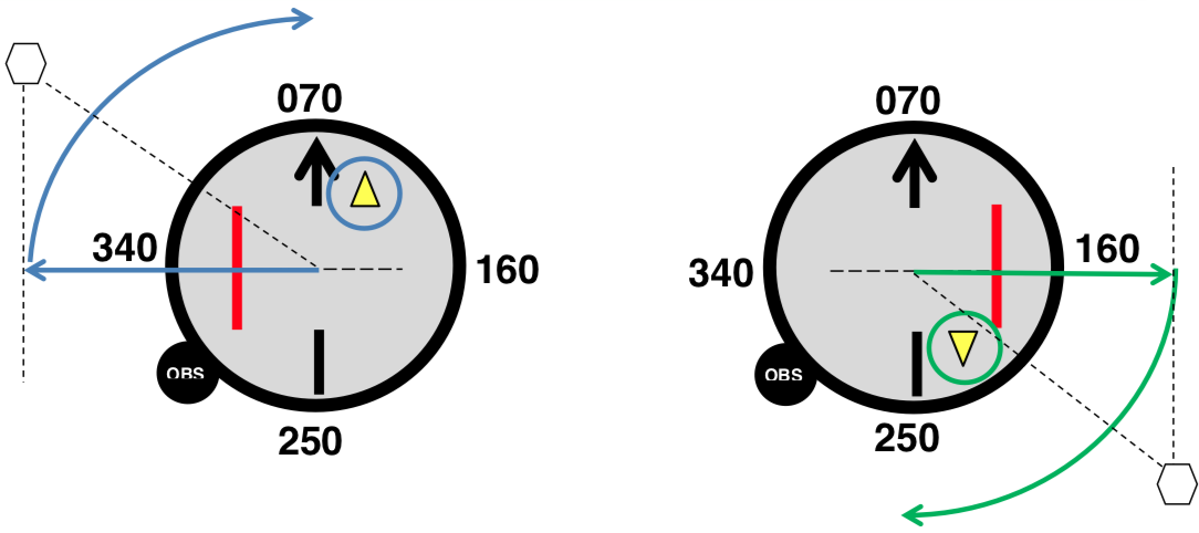
In the left figure above, the shortest path to join the VOR radial is 340° (=070°-090°) (blue straight arrow). The VOR is located in the sector between 340° and 070° as we are in the TO region.
In the right figure above, the shortest path to join the VOR radial is 160° (= 070° +090°) (green straight arrow). The VOR is located in the sector between 160° and 250° as we are in the FROM region.
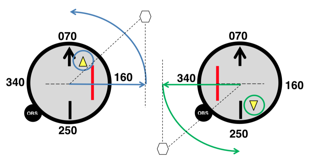
In the left figure above, the shortest path to join the VOR radial is 160° (= 070° +090°) (blue straight arrow). The VOR is located in the sector between 160° and 070° as we are in the TO region.
In the right figure above, the shortest path to join the VOR radial is 340° (=070°-090°) (green straight arrow). The VOR is located in the sector between 340° and 250° as we are in the FROM region.
Pay attention that the reading is in function of the radial course and not the heading of the aircraft. The aircraft can have a very different heading from the radial course!
On the HSI instrument, you can use the same method using the select course pointer as reference for direction to find the VOR location quadrant. In our example below, the VOR is located between heading 240° and 330°.
- Course Deviation Indicator - CDI
- [VHF Omnidirectional Range - VOR (Instrument)]
- None
- VID 150259 - Creation
- VID 450012 - Update
- VID 496402 - Wiki.js integration