¶ Introduction
This is the segment in which alignment and descent for landing are made.Normally, final approach may be made to a runway for a straight-in landing, or to an aerodrome for a visual manoeuvre (circling).
¶ Straight in and circling approach
There are 2 categories of approach:
- Straight-in
- Circling
A straight-in approach is aligned with the runway centre line.
In case of non-precision approach, a straight-in approach is considered acceptable if the angle between the final approach track and the runway centre line is 30° or less.
In case of precision approach, the straight-in approach aligned with the runway centre line is mandatory.
A circling approach is an extension of an instrument approach procedure which provides for visual circling of the aerodrome prior to landing.
A circling approach is specified in those cases where a straight-in approach is not possible. The criteria can be:
- Terrain or other constraints cause the final approach track alignment is not possible with the runway centre line inside the 30° tolerance.
- Descent gradient is not compatible with landing using straight-in approach
¶ Types of final approach
The criteria for final approach vary according to the type. These types are:
- Non precision approach (NPA) with final approach fix (FAF)
- Non precision approach (NPA) without final approach fix (FAF)
- Approach with vertical guidance (APV)
- Precision approach (PA)
¶ Categories of precision approaches
| Category of Operation | Decision Height (DH) | Runway Visual Range (RVR) |
|---|---|---|
| CAT I | DH ≥ 200 ft (60m) | RVR ≥ 550 m or VIS ≥ 800m RVR ≥ 1750 ft or VIS ≥ 2400 ft |
| CAT II | 100 ft ≤ DH < 200 ft | RVR ≥ 300 m |
| CAT IIIA | No DH or DH < 100 ft | RVR ≥ 175 m |
| CAT IIIB | No DH or DH < 50ft | 50 m ≤ RVR < 175 m |
| CAT IIIC | No DH | No RVR limitation |
¶ Non precision approach with FAF
A Non-precision approach (NPA) procedure is an instrument approach procedure designed for 2D instrument approach operations Type A.
The FAF is sited on the final approach altitude to the appropriate MDA/H either for a straight-in approach or for a visual circling. The distance for locating the FAF relative to the runway threshold is:
- 9.3km (5NM) as optimum distance
- 5.6km (3NM) as minimum distance
- 19km (10NM) as maximum recommended distance
The optimum final descent gradient for a non-precision approach shall be 5.2% (3°), providing a rate of descent of 52m per kilometre (318ft per NM). This value is published on charts. The maximum standard descent gradient for non-precision procedures with FAF is:
- 6.5% for category A and B aircraft
- 6.1% for category C, D and E aircraft
- 10% for category H, helicopter
Non-standard procedures published with a final approach descent gradient greater than these values can exist and it requires a special approval by the national competent authority.
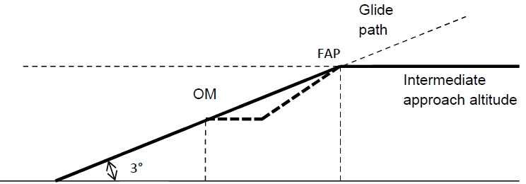
The FAF is crossed at the procedure altitude in descent but no lower than the minimum crossing altitude associated with the FAF. The descent is normally initiated prior to the FAF in order to achieve the prescribed descent gradient/angle.
Delaying the descent until reaching the FAF at the procedure altitude will cause a descent angle to be greater than 3° (see image below).

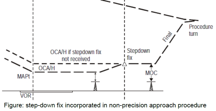
A step-down fix may be incorporated in some non-precision approach procedures. In this case two obstacle clearance altitude/heights (OCA/H) are published (look at the image on the next page):
- A higher value is applicable to the primary procedure until the step-down fix.
- A lower value is applicable only if the step-down is positively identified during the approach.
Where a step-down procedure using a suitably located DME is published, the pilot shall not begin descent until established on the specified track. Once established on track, the pilot shall begin descent while maintaining the aeroplane at or above the published DME distance/height requirement.

¶ Non precision approach without FAF
Sometimes an aerodrome is served by a single facility (like NDB) located on or near the airfield and no other facility is suitably situated to form a final approach fix (FAF). This is the case to have a non-precision approach without FAF.
A procedure may be designed where the facility is both IAF and the MAPt. These procedures indicate:
- A minimum altitude/height for a reversal procedure or racetrack
- An OCA/H for final approach
In the absence of a FAF, descent to MDA/H is made once the aircraft is established inbound on the final approach track.
Procedure altitude/heights will not be developed for non-precision approaches without a FAF. In the non-precision approach without FAF procedures, the final approach track cannot normally be aligned on the runway centre line.
¶ Vertical path control on non-precision approach procedures
Aircraft pilots should reduce the controlled flight into terrain (CFIT) by using standardization in vertical path control on non-precision approach procedures.
They typically employ one of 3 techniques for vertical path control on non-precision approaches:
- Continuous descent final approach (CDFA)
- Constant angle descent
- Step-down descent
Continuous descent final approach (CDFA) is a continuous descent, flown either with VNAV guidance calculated by on-board equipment or based on manual calculation of the required rate of descent without level-offs.
The rate of descent is selected and adjusted to achieve a continuous descent to a point approximately 15m (50ft) above the landing runway threshold or the point where the flare manoeuvre should begin.
CDFA technique simplifies the final segment of the non-precision approach by incorporating techniques similar to those used when flying a precision approach procedure or an approach procedure with vertical guidance. The CDFA technique is preferred and used whenever possible as it adds to the safety of the approach operation by reducing pilot workload and lessening the possibility of error in flying the approach.
The constant angle descent is a unbroken angle of descent from the final approach fix (FAF) or optimum point on procedures without a FAF to a reference datum above the runway threshold (e.g. 15m (50ft)).
The step-down descent involves an expeditious descent and is described as descent immediately to not below the minimum step-down fix altitude or MDA/H. This technique is acceptable as long as the descent gradient remains less than 15% and the missed approach is initiated at or before the MAPt.
Careful attention to altitude control is required due to the high rates of descent before reaching MDA/H and because of the increased time of exposure to obstacles at the MDA.
¶ Precision approach
A precision approach (PA) procedure is an instrument approach procedure based on navigation systems (ILS, MLS, GLS and SBAS CAT I) designed for 3D instrument approach operations Type A or B.
Lateral and vertical guidance refers to the guidance provided either by:
- Ground based navigation aid
- Computer-generated navigation data
In our public simulator, only the instrument landing system is simulated as a precision approach using radio navigation aids. Modern and advanced aircraft in our public simulator can simulate the new procedure localizer performance with vertical guidance (LPV).
The final approach segment begins at the final approach point (FAP). This is a point on the final approach track where the intermediate approach altitude intercepts the nominal glide path.
The intermediate approach altitude generally intercepts the glide path at heights from 300m (1000ft) to 900m (3000ft) above runway elevation.
For a 3° glide path, interception occurs between 6km (3NM) and 19km (10NM) from the threshold.
The intermediate approach track or radar vector is designed to place the aircraft on the localizer for the final approach track at an altitude that is below the nominal glide path.

The final approach area contains a fix or a facility that permits verification of the glide path versus altimeter relationship. The outer marker or equivalent DME fix is normally used for this purpose. After the final approach point, descent may be made on the glide path to the altitude of the published fix crossing.
Descent below the fix crossing altitude should not be made prior to crossing the fix.
In the event of loss of glide path elevation angle guidance during the approach, the procedure becomes a non-precision approach. The OCA/H published for the glide path inoperative will then apply.
Minimum requirement to make a standard precision approach with an ILS:
- ILS Category I must be flown with pressure altimeter
- ILS Category II must be flown with pressure altimeter, radio altimeter and flight director
- Missed approach climb gradient is 2.5%
- Glide path angle is
- Optimum = 3°
- Minimum = 2.5°
- Maximum = 3.5°
Non standard procedures are those involving a glide path greater than 3.5° or any angle when the nominal rate of descent exceeds 5m/s (1000ft/min).
Non-standard procedures are normally restricted to specifically approved operators and aircraft.
The protection area of a precision ILS approach assume that the pilot does not normally deviate from the centre line more than half-scale deflection after being established on track.
¶ Approach procedure with vertical guidance (APV)
An approach procedure with vertical guidance (APV) is a performance-based navigation (PBN) instrument approach procedure designed for 3D instrument approach operations Type A.
Lateral and vertical guidance refers to the guidance provided either by:
- Ground based navigation aid
- Computer-generated navigation data
RNAV (LNAV/VNAV) approach procedure based on GPS is an APV approach. In this case, the use of a VNAV system such as baro-VNAV is required. When baro-VNAV is used, the lateral navigation guidance is based on the RNP APCH and RNP AR APCH navigation specifications.
This APV approach benefits over advisory VNAV guidance being overlaid on a non-precision approach, as they are based on specific procedure design criteria:
- Height loss after initiating a missed approach allowing the use of a DA instead of an MDA, thereby standardizing flight techniques for vertically guided approach operations
- Obstacle clearance throughout the approach and landing phase taking into account temperature constraints down to the DA, therefore resulting in better obstacle protection compared to a non-precision approach procedure.
- IFR arrival and approach procedure
- IFR Approach procedure - Intermediate approach segment
- IFR Approach procedure - Missed approach segment
- ICAO Documentation 8168 - Aircraft Operations - Volume I - Flight Procedures - 6th Edition 2010 - Section 4 - Chapter 5
- VID 150259 - Creation
- VID 531824 - Wiki Integration
- VID 496402 - Wiki.js integration