¶ Introduction
The field of inertial navigation is a well-established field of study and yet extends. The first inertial sensors were developed and tested by rocket designers such as Robert Goddard and Wernher von Braun in the arly 1930s. Later inertial sensors technology was perfected by institutions such as Drapers Labs, creating the first Inertial Navigation Systems. Inertial navigation made possible many of the great achievements such as use with the advent of spacecraft, guided missiles, and commercial airliners.
¶ Basics
The basic principle behind inertial navigation is straightforward.
Starting from a known point, you calculate your present position from the direction and speed traveled since starting navigation. Generally this process is known as dead reckoning.
Dead Reckoning is a type of navigation from a known starting point and then, by using vector information (direction and speed) against a clock, an estimate of the current position can be made.
Therefore, inertial system is a continuously running dead reckoning.
¶ Measurement
The difference between other navigation systems and inertial systems is how it determines direction, distances, and velocities. Inertial systems come in all shapes and sizes, but one thing they have in common though is their use of multiple inertial sensors, and some form of central processing unit to keep track of the measurements coming from those sensors.
We can highlight 5 basic components of typical inertial systems:
- Three linear accelerometers arranged orthogonally to supply X, Y, and Z axis components of acceleration.
- Gyroscopes to measure and use changes in aircraft vector to maintain and orient the stable platform.
- A stable platform oriented to keep the X and Y axis linear accelerometers oriented north-south and east-west to provide azimuth orientation and to keep the Z axis aligned with the local gravity vector (we will talk about another platform design called strap-down later)
- Integrators to convert raw acceleration data into velocity and distance data.
- A computer to continuously calculate position information.
¶ Accelerometers
Acceleration-measuring devices are the heart of all inertial systems. It is important that they function reliably for all manoeuvres within the capability of the aircraft.
As you can guess from their name, accelerometers measure acceleration, not velocity.
Let's assume 2 main requirements for accelerometers:
- Very slight accelerations and changes in heading in all directions must be detected.
- Changes in temperature and pressure must not affect INS operation.
¶ Linear accelerometer
The simplest type of linear accelerometer consists of a pendulous mass that is free to rotate about a pivot axis in the instrument. There is an electrical pickoff that converts the rotation of the pendulous mass about its pivot axis into an output signal.Since the signal is proportional to the measured acceleration, it is sent to the navigation computer as an acceleration output signal.

To obtain acceleration in all directions, three accelerometers are mounted mutually perpendicular in a fixed orientation.
¶ Gyroscopes
Accelerometers are great at measuring straight line motion, but they are no good at rotation - that's where gyroscopes come in. Gyros don't care about linear motion at all, only rotation.
Gyroscopes are used in inertial systems to measure angular acceleration and changes in orientation and heading.
Over the years of usage and research the original gimbaled gyroscopes have been replaced by newer designs. Let's briefly talk about them.
¶ Gimbaled gyroscopes
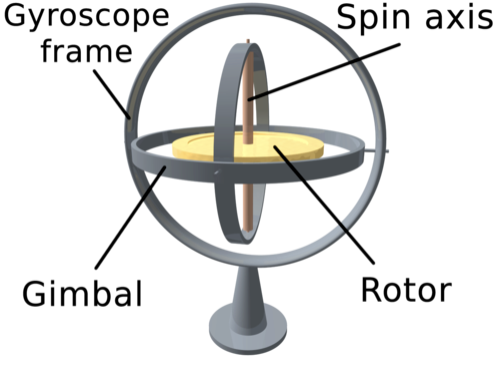
In a traditional sense, a gyroscope employs one or more spinning rotors held in a gimbal or suspended in some other system that is designed to isolate it from external torque. That type of gyroscope works because once the rotor is spinning, it wants to maintain its axis or rotation.
A gimbal uses a number of concentric rings mounted inside one another that are connected via orthogonally arranged pivots. This design allows the gyro to freely rotate in three-axes.
¶ Electronically suspended gyroscopes
These gimbal-less gyroscopes consist of a ball that is suspended in a magnetic field and spun electronically. Evacuating the air in the gyro cavity further reduces friction. Optical sensors measure the ball's orientation from symbols etched on the surface of the ball. The result is a near frictionless gyro with precession rates measured in years.
¶ Ring Laser Gyro
Accuracy and dependability of first generation systems have greatly improved with the introduction of the ring laser gyro (RLG).
Technically, the RLG is not a gyroscope since it has no moving parts, but it gives the same information as a gyro.
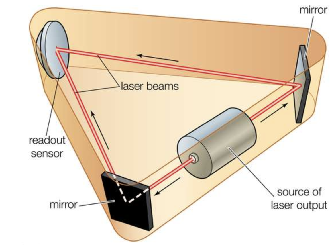
A RLG is made from a single block of glass with three holes drilled through the glass to form a triangular path. Two of the openings are plugged with mirrors and the triangular tube is filled with helium, neon or other lazing gas. When the gas is charged, the lazing gas produces two counter-rotating laser beams that are reflected around the path by the mirrors. Both laser beams emerge through the third hole in the glass and are superimposed upon each other to produce an interference pattern.
As the RLG moves, one beam has a longer path to travel, the other a shorter path. This causes changes in the interference pattern that are detected by photocells. The angular rate and direction of motion are computed as accelerations.
¶ Acoustic gyroscopes
Another recent development is the inertial sensor based on vibrating quartz crystal technology. Like the RLG, these are not true gyros. Acoustic gyros are manufactured from a single piece of microminiature quartz rate sensor. Angular accelerations affect the patterns produced by a vibrating tuning fork and result in torque on the fork proportional to the angular acceleration. These gyros appeared in inertial units in the late 1990s.
¶ Stable platform vs strap-down platform
Of the many different designs of inertial systems, each with different performance characteristics, there are two main categories used in aircraft: stable platform and strap-down.
¶ Stable platform
As we discussed earlier, three accelerometers are mounted on a platform and orientated (usually) north/south, east/west, and up/down. This platform is driven by gyros (two or three) to always maintain its alignment with these axes regardless of any movement of the aircraft. Analogue feeds can be taken directly from the accelerometers and gyros that are in direct proportion to acceleration, and changes in velocity and direction.
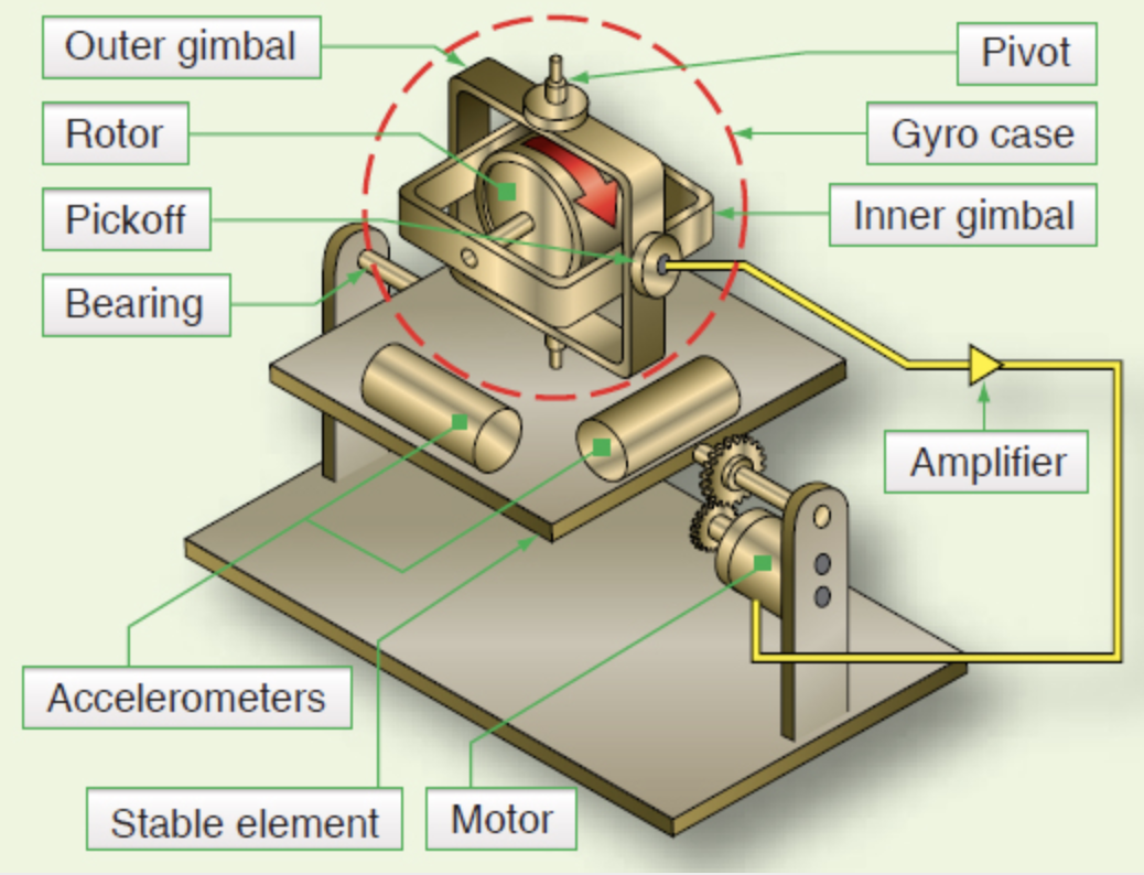
Disadvantages: because of the mechanical assembly and many moving parts, stabilised platform INS suffer from wear and tear, and friction causes the output to "drift" over time. Compensation for drift requires complex bearing assemblies and special lubricants. Maintenance of stabilised platform INS is complex, costly and time-consuming.
¶ Strap-down platform
RLG and accelerometers are attached rigidly, or "strapped down", to the frame of the aircraft i.e. as the aircraft moves, so does the inertial system platform - exactly. Three gyroscopes sense the rate of roll, pitch, and yaw and three accelerometers detect accelerations along each aircraft axis. It integrates them to get the orientation, then mathematically calculates the acceleration of the north/south, east/west and up/down axes, as a gimballed system would.
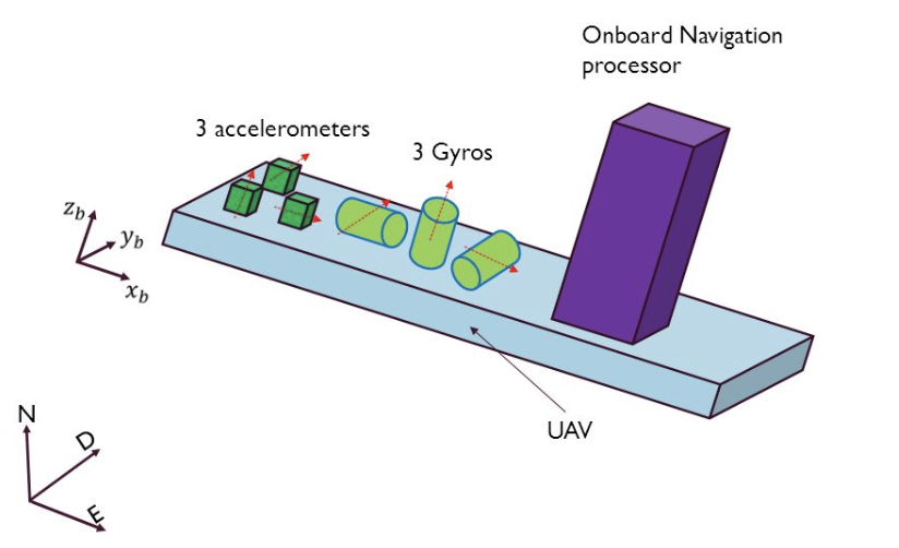
The advantages of reduced cost, size, weight and reliability make these systems the preferred choice of inertial system for many aircrafts.
¶ Accuracy and limitations
Inertial systems accuracy will drift with time. This can occur for many different reasons. Older stabilised platform inertial systems (1970's and early 1980's) may have position errors of 2 nm/hr. Modern strap-down LRG in inertial systems tend to have error rates of 0.6 nm/hr.
Inertial systems generally are not the sole means of navigation on commercial airliners. Position errors can be reduced by frequent updates of position from GPS and ground-based navigation aids.
Let's get through those typical position errors:
- Drift. It is mostly associated with imperfections. In stable platform, these imperfections exist within gyro bearings and mass imbalances. In strap-down RLG devices, the cause is derived almost entirely from imperfections in the mirrors and their coatings.
- Transport Wander. A gyro will attempt to maintain it's original alignment with the Earth. When the aircraft moves across the globe, the local horizontal reference changes and this will create an angle with a gyro. This error is known as Transport Wander and also Apparent Drift. It is usually corrected by signals derived from the INS Latitude and Longitude.
- Earth Rotation. Inertial system detects Earth's rotation when moving. The final movement detected will be a combination of both the aircraft's movement and the Earth's rotation. These errors are small and can be compensated for.
- Coriolis. As an aircraft travels from A to B around the globe it actually will follow a curved path (or a series of shorter curved paths). An INS will detect this as turning and an error can be introduced.
¶ Inputs and outputs
¶ Inputs
Although an inertial system is a "self-contained" navigation system, it does perform better when provided with some data inputs to compensate for position errors and increase accuracy. These may include:
- Initial Position as the "shut-down" position will undoubtedly carry some error.
- GNSS (GPS) Position bounding the INS position error.
- Barometric Altitude helps to stabilise the vertical velocity and inertial altitude outputs.
- True Air Speed (TAS) allows for the calculation of Wind Speed and Direction.
¶ Outputs
Typical inertial system outputs fed to other aircraft avionics and systems include, but are not limited to:
- Pitch and Roll
- True and Magnetic Heading
- True Air Speed (TAS) and Ground Speed (G/S)
- Latitude, Longitude and (inertial) Altitude
- Wind Speed and Direction, and Drift Angle
- Pitch, Roll and Yaw
- Vertical Speed and Rate
¶ Alignment
Inertial systems usually require an initialisation process that establishes the relationship between the aircraft (the reference axes) and the geographic reference (position and orientation). This process is called alignment.
Alignment usually requires the aircraft to remain stationary for a period of time in order to initialise fully. It also will normally require the input of certain data from another system or from a manual entry.
Alignment can be achieved independent of any external data. This is known as self-alignment. Or the alignment process can be speeded up with data supplied from a GPS or other systems, and even manual entry.
¶ Pilot interface
Aircraft manufacturers usually establish an approach to interact with the onboard inertial system. Here we go through an example of a Boeing 737 NG Inertial Reference System (IRS) interface. It's located on the aft overhead panel and includes IRS Display and IRS Mode Selector Unit.
For other aircraft please refer to the appropriate flight/operational manuals.
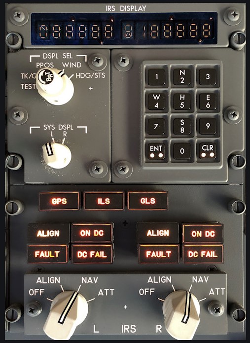
¶ IRS Display
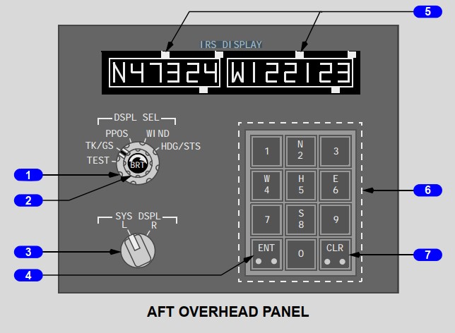
1 - Display Selector control. Allows to select information to display:
- TK/GS - true course and ground speed;
- PPOS (stands for "Present POSition") - current latitude and longtitude;
- Wind - true wind direction and speed ;
- HDG/STS - true heading and maintenance status codes.
2 - Brightness control. Adjusts brightness of the data displays.
3 - System Display Selector. Selects one of the two IRSes for the data displays.
4, 6, 7 - Enter Keyboard
5 - Data Displays Two windows display data for the IRS selected with the system display selector.
¶ IRS Mode Selector Unit
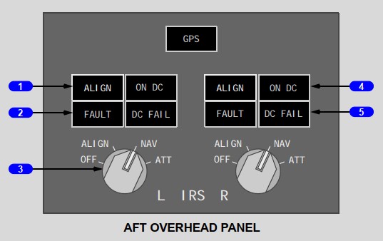
1,2,4,5 - Information lights.
3 - Inertial Reference System Mode Selector
- OFF selector;
- ALIGN - initiates the alignment cycle;
- NAV - system enters the NAV mode after completion of the alignment cycle and entry of present position;
- ATT - provides only attitude and heading information.
- None
- OxTS article - Inertial navigation systems
- Skybrary.aero - Inertial navigation system
- Boeing 737NG FCOM
- VID 531824 - Creation
- VID 496402 - Wiki.js integration