¶ Introduction
The Instrument Landing System (ILS) is the most precise navigation equipment used in IFR flight. It is today the most used precision approach system in our current flight simulators.
It is composed of at least two of the following elements:
- A Localizer (LOC) which provides the horizontal deviation with respect to the runway axis. The LOC frequencies range between 108.10 MHz and 111.95 MHz (with the 100 kHz first decimal digit always odd) and are not used for any other purpose.
- A Glide Slope (GS, or Glide Path GP) which provides the vertical deviation with respect to the nominal approach slope (most commonly 3°). The GP signal is in the 330 MHz (UHF) range.
Together with the previous, two other pieces of equipment can be also available:
- A DME which provides the distance between the LOC and the airplane
- A (set of) MARKER beacon(s) which provides a light and a sound indication at a published distance from the runway threshold.
The certified range is 15-20 NM (25 NM in flight simulator) for the LOC and slightly less for the GS. The glide information is not reliable anymore when going below 50ft AGL.
In practice, the pilot sets only the LOC frequency since the GS (and eventually the DME) frequencies are paired to the LOC frequency.
The Localizer (LOC) provides only one of the two fundamental functions of an ILS. However, some small airports do not dispose of a full ILS but only the localizer part.
Read more about the Instrument Landing System - ILS (Beacon) here !
¶ On-board equipment: ILS
The on-board equipment controls demodulating the VHF ILS signal in order to get the amplitude of the 90Hz and 150z modulation.
¶ Frequency selector
The navigation receiver is the control unit where pilots select the ILS frequency. The ILS frequency should be usually entered on the NAV 1 selector.

These images above show a Beechcraft (at the left), a Cessna (at the centre) and a Boeing (at the right) Selector.
NAV1 equipment has its own controls:
- Frequency selector: frequency is tuned by rotating 2 knobs until the wanted frequency is obtained.
One knob for the main digits and another for decimal digits. You can tune on the smallest aircraft the wanted frequency directly, or tune a standby frequency (non-active)
- Band selector on heavier aircraft (Airbus, Boeing)
- Mode selector (NAV, DME ...) on light aircraft
- Frequency switch between Active frequency and standby frequency (only when standby frequency exists)
¶ Indicator instruments
The ILS signal is analyzed by a receiver and displayed by:
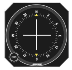
- A Course Deviation Indicator (CDI).
- A Horizontal Situation Indicator (HSI)
- An Electronic Horizontal Situation Indicator (EHSI) named Navigation Display (ND)

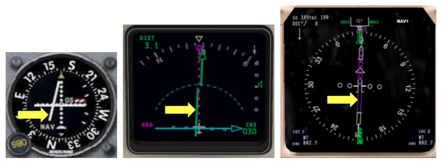
The localizer indicator is represented by a vertical indicator, using a vertical line, a vertical bar or a vertical rectangle, which can move from left to right inside the instrument around the middle of the instrument (centered position).

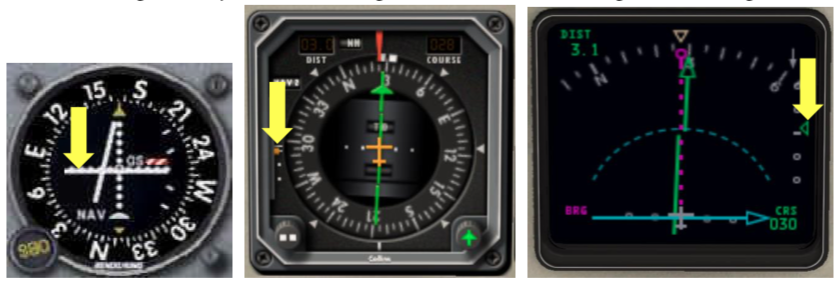
The glide path indicator is represented by
- A horizontal indicator, using a horizontal line or a horizontal bar which can move from top to bottom position inside the instrument around the middle of the instrument (centered position).
- A small triangle or square next to a graduation bar on the right or left edge of the instrument

¶ Position of aircraft and display in the cockpit
¶ Aircraft on localizer optimal path

The aircraft is exactly on the optimal path direct to the runway. No
lateral shift is noticed. The localizer vertical indicator on the
navigation instrument is at the centre position.
¶ Aircraft at the left of localizer optimal path

The aircraft is at the left of the optimal path direct to the runway.
Lateral shift is noticed. The localizer vertical indicator on the
navigation instrument is on the right. The centre of the instrument
shall be taken as the aircraft direction and the localizer indicator
represents the optimal path. In order to join the optimal path, the
pilot shall turn to the right towards the indicator.
¶ Aircraft at the right of localizer optimal path

The aircraft is at the right of the optimal path direct to the runway.
Lateral shift is noticed. The localizer vertical indicator on the
navigation instrument is on the left. The centre of the instrument shall
be taken as the aircraft direction and the localizer indicator
represents the optimal path. In order to join the optimal path, the
pilot shall turn to the left towards the indicator.
¶ Aircraft on glide slope optimal path
 !
!
The aircraft is exactly on the optimal path direct to the runway. No
vertical shift is noticed. The glide slope horizontal indicator on the
navigation instrument is at the centre position.
¶ Aircraft below glide slope optimal path

The aircraft is below the optimal path direct to the runway. Vertical
shift is noticed. The glide slope horizontal indicator on the navigation
instrument is above the centre of the instrument. The centre of the
instrument shall be taken as the aircraft direction and the glide slope
indicator represents the optimal path. In order to join the optimal
path, the pilot shall stop his descent until he reaches the optimal
descent path.
¶ Aircraft above glide slope optimal path

The aircraft is above the optimal path direct to the runway. Vertical
shift is noticed. The glide slope horizontal indicator on the navigation
instrument is below the centre of the instrument. The centre of the
instrument shall be taken as the aircraft direction and the glide slope
indicator represents the optimal path. In order to join the optimal
path, the pilot shall increase the descent rate or lower thrust power
until he reaches the optimal descent path.
¶ Optimal ILS descent path

In order to maintain the optimal descent path, the pilot shall keep the
ILS instrument centred like the image until the ILS procedure minima or
the visual reference is acknowledged.
- None
- VID 150259 - Creation
- VID 450012 - Update
- VID 496402 - Wiki.js integration