¶ Introduction
When an air traffic controller has such an amount of traffic in his approach area that he cannot handle more traffic for a determined or non-determined period of time, the air traffic controller can use the holding pattern to put the traffic on hold before taking them into account inside his approach sequence.
¶ Holding pattern and stacking process
¶ Holding pattern
A holding pattern is:
- Constituted of 2 half turns joined by a straight flight leg. The straight flight length is generally 1 minute flight duration or a distance based on a DME.
- Constituted of a reference fix where the holding pattern starts and where an aircraft can exit to continue the next procedural approach phase of the flight. The turn in the holding pattern is a right turn (like the figure below) by default but it can be published to the left.
- Flown at a certain altitude with a maximum speed restriction where an aircraft can exit to continue the next procedural approach phase of the flight.
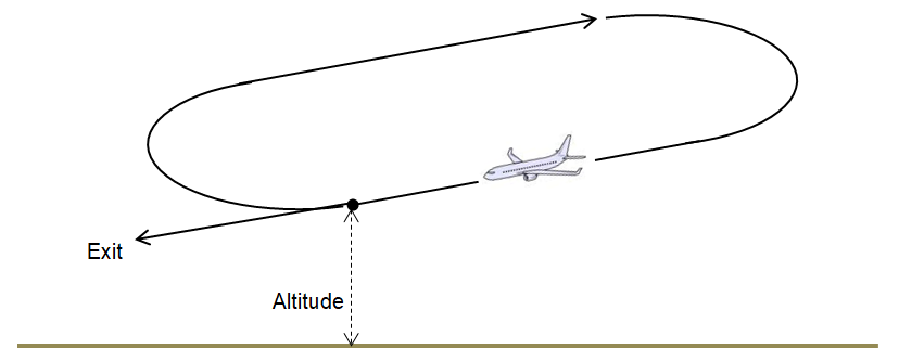
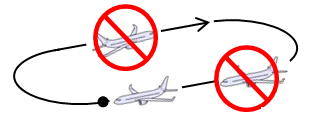
The problem of this holding pattern is that only one aircraft can use the holding pattern at the published altitude.
If an air traffic controller (ATC) has several aircraft to put on hold, he cannot use the same holding pattern at the same altitude to handle several aircraft. In this case, ATC shall create a holding stack.
¶ Holding stack
When an air traffic controller (ATC) wants to put on hold several aircraft, he can create a holding stack. A holding stack is the superposition of holding patterns using the same holding reference fix but flown at different altitudes and separated using adequate vertical separation:
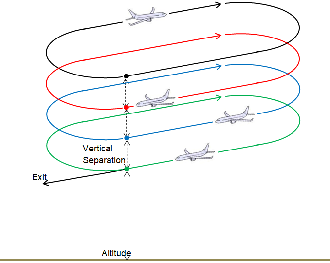
The vertical separation should be the minimum IFR separation (which is 1000ft below FL290), or above
¶ Management
We shall discuss the following situation:
- ATC creates a holding stack
- ATC fills the stack with aircraft
- ATC removes aircraft from the stack
- ATC needs to create a multi stack
- ATC manages stack in function of separation altitude
¶ Creating a holding stack
An ATC will create a holding stack when he cannot integrate an aircraft into the approach sequence.
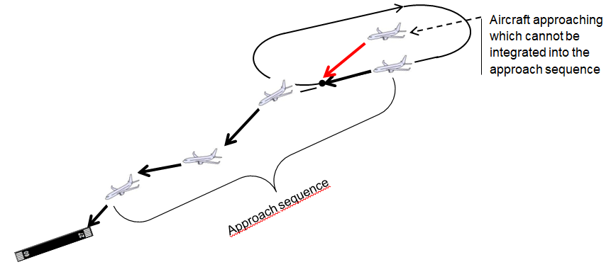
On charts, holding patterns are usually published at the initial approach fixes (IAF) which is the end of the arrival phase of flight, and before starting the approach phase. This point associated with the published holding pattern should be taken as holding stack reference point where the air traffic controller starts to construct his waiting stack.
¶ Filling the stack with aircraft
A holding stack shall be considered as a FIFO system. FIFO means FIST-IN FIRST-OUT. In our application, this means that the air traffic controller puts the aircraft in the stack by order of arrival, in order to remove them using the same order.
Remember the goal of the air traffic controller in an approach area: he takes the aircraft arriving at high level and controls them to delivery on the final approach path at lower altitude. Arriving aircraft should have a higher altitude than aircraft in the approach sequence.
In conclusion, as the controller should put them in the holding stack by order , he shall stack the aircraft using the lowest altitude available above the preceding aircraft which is inside the stack.
Remember that the controller will use one aircraft per altitude used in the stack.
An aircraft shall be inserted inside the stack at the reference point
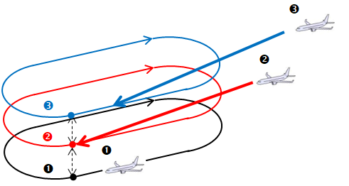
In our example, the first aircraft is on the first floor of the holding stack. The second aircraft shall be inserted on the second floor above the first one. The third aircraft shall then be inserted on the third floor above the second one.
¶ Removing aircraft from the stack
In the previous chapter, we said that the stack should be considered as a FIFO system so; the traffic controller puts the aircraft in the stack by order of arrival, in order to remove them using the same order. The controller will remove aircraft from the first floor of the holding stack, or the aircraft with the lowest altitude in the stack and normally when the aircraft is on the inbound leg of the holding pattern.
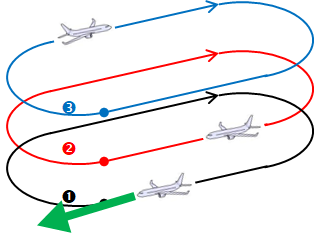
In our example, the aircraft at the first floor will exit the stack at first. The air controller should then insert this aircraft into the approach regulation sequence.
ATC can remove aircraft from the first floor anywhere from the pattern if the approach regulation sequence requires so.
The reasons to choose the first floor of the holding stack or the lowest altitude is:
- altitude is more compatible with the next approach phase of flight than higher altitude
- no conflict is possible with other aircraft in the stack if the lowest altitude is selected
After the aircraft has left the stack, we need to reorganize the stack using the free holding floor. At this stage, the air traffic controller shall descend each aircraft one by one down to the next free level, taking vertical separation into account.
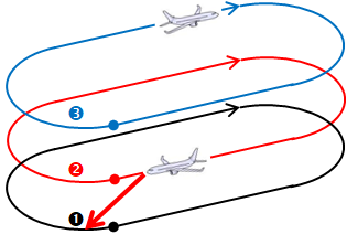
In our example, the aircraft at the second floor will first descend to the next lower level (first floor).
The aircraft at the third floor shall maintain his altitude until minimum vertical separation will be guaranteed by the air traffic controller.
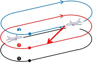
In our example, the aircraft at the third floor will descend to the next lower level (second floor) as the lower aircraft has reached the first floor and the second floor is free
This management should descend all aircraft in the stack and clear the higher level(s) to incoming aircraft.
If the two consecutive floors are separated by vertical separation minimum, we advise air traffic controllers to allow the descent when the lower aircraft has effectively reached its new level.
The air traffic controller can anticipate the descent but he shall take into consideration aircraft performance and pilots' speed of response.
¶ Multi stack creation
If an air traffic controller uses a published holding pattern to create his stack, he should be limited by the protection area of this holding pattern. The protection area is an altitude where the holding patterns are not protected against other IFR routes and procedures. The air traffic controller can use levels above this protected area but the situation needs extra safety management in order to ensure protection of these levels.
Furthermore, the approach controller is limited by his area of responsibility. In conclusion, the number of traffic to insert inside the stack is limited by the maximum altitude of his area of responsibility.
In addition, the approach controller can handle arrivals which come from different directions and IAF.
In all these situations, the approach controller can create a multi stack in his area of responsibility or create linked stacks with the en-route traffic controller .
¶ Several Stacks
In the figure below, there is an example of several holding stacks creation over different fixes in the approach area. The air traffic controller can handle each holding stack separately.
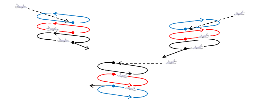
The air traffic controller should verify and maintain separation between every holding stack with others at all times if they are not all published.
¶ Linked Stacks
As the approach area is limited in terms of altitude, the stack is also limited for its maximum altitude. If we have too many aircraft to stack, the higher controller (en-route controller) can initiate another stack before the approach area.
These stack altitudes should be higher than the previous stack.
Separation should be done by the air traffic controller between all stacks.
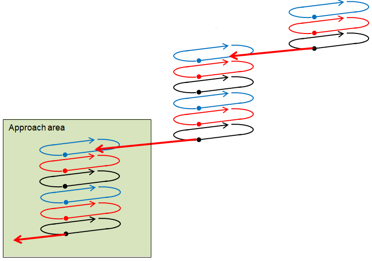
If the stacks are laterally separated, the higher level of the lower stack floor should be inferior or equal to the lower level of the next stack floor.
If the ATC thinks that the stacks separation is not granted at all times and for any aircraft, the higher level of the lower stack floor should be inferior to the lower level of the next stack floor and separated by minimum vertical separation considered in the airspace (1000ft below FL290).
¶ Managing a stack in function of separation altitude
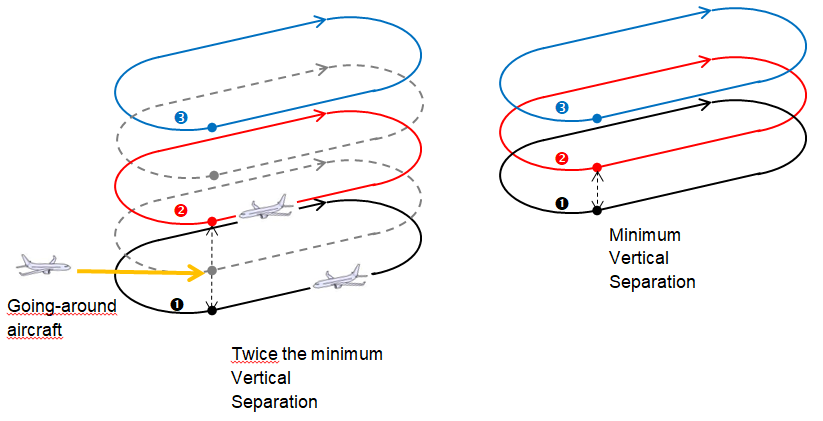
The air traffic controller is not limited to use minimum vertical separation (1000ft below FL290) between all floors inside a holding stack. The air traffic controller can use twice the minimum vertical separation (2000ft below FL290) in order to separate the floors in the holding stack.
Using twice the minimum vertical separation is a solution for ATC:
- To prevent aircraft to create conflict alerts when aircraft crew select a wrong altitude or making an undershoot of altitude during descent.
- To also have free spare levels in order to integrate the going around aircraft inside the holding stack.
¶ En-route holding to prevent overload and stack creation
The creation of a holding stack should be the ultimate solution for an approach controller in order to handle too much traffic.
Each controller has a part of the responsibility to prevent the holding stack creation.
In real life, each aircraft is regulated from the clearance given on the ground until its arrival on the approach area. Complex systems calculate arrival estimations of each flight in order to anticipate the overflow of controlled areas. In IVAO, we do not have such complex systems, but ATC to ATC communication should be used to share the overflow situation at some destinations. When desired, the en-route controller can create pre-regulation sequences by reducing the speed of aircraft or by using an en-route holding pattern (see below) in order to create delay.

- None
- VID 150259 - Creation
- VID 256272 - Wiki integration
- VID 496402 - Wiki.js integration