¶ Introduction
A VHF Omnidirectional Range (VOR) beacon is a short-range radio-navigation system enabling aircraft with a receiving unit to determine their position and stay on a given course.
A VOR receiver enables the aircraft to determine its bearing with respect to the beacon (the position of which is known). From the phase shift measurement, the VOR receiver enables to determine the direction in degrees, called the radial, from the station to the aircraft.
The VOR beacon simultaneously transmits two signals, a constant omnidirectional signal called the reference phase and a directional signal which rotates through 360°, during a 0.03 second system cycle, and consistently varies in phase through each rotation. The two signals are only exactly in phase once during each rotation – when the directional signal is aligned to magnetic north.
VOR are exploited over the Very High Frequency (VHF) band from 108 to 117.95 MHz with channels spaced of 50 or 100 kHz (50 kHz for dense zones, 100 kHz elsewhere). The first 4 MHz is shared with the ILS (Instrument Landing System) band, the VOR being allocated to 160 of the 200 available channels. To leave channels for the ILS, in the range 108.0 to 111.95 MHz, the 100 kHz digit is always even. Of these 160 channels, 120 are allocated to VOR stations intended for en route navigation while the other forty are for terminal VOR stations.
¶ Type of VOR beacon
Two types of VOR beacons are used:
- Terminal VOR (T-VOR): it is used in the terminal area of airports and covers a relatively small geographic area protected from interference by other stations on the same frequency. T-VOR output power is 50 W which allows covering a region from 1000 ft AGL up to and including 12000 ft AGL at radial distances out to 25 NM. The allocated band ranges from 108 to 111.850 MHz with the 100 kHz digit being always even.
- En route VOR: they are used as route fixes within high or low airspace. Their output power is 200 W which provides a range up to 200 NM. The allocated band ranges from 112 to 117.950 MHz
The VOR station is often coupled to a DME system to provide a distance measurement between the aircraft and the beacon.
Read more about the VHF Omnidirectional Range - VOR (Beacon).
¶ On-board equipment: VOR
The VOR signal is analysed by a receiver and displayed by:
- A course deviation indicator (Course Deviation Indicator - CDI) with or without Glide slope indication
- A horizontal situation indicator (HSI)
- An electronic horizontal situation indicator (EHSI) named navigation display (ND)
- A radio magnetic indicator (RMI)
¶ Course Deviation Indicator - CDI
The CDI is found in most training aircraft.
In the CDI instrument, the radial indicator is a needle which can be distinguished on the top of the instrument.
- If the location of the aircraft is to the left of course, the needle deflects to the right
- If the location of the aircraft is to the right of course, the needle deflects to the left
- If the location of the aircraft is on the right course, the needle is centred (see figure below).
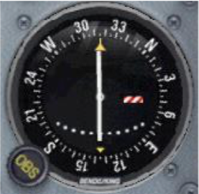
A mobile compass is present and can be rotated by using the omnibearing knob usually written as ”OBS”:
When the course selector is rotated, the instrument moves the needle to indicate the position of the radial relative to the aircraft. If the course selector is rotated until the deviation needle is centred, the radial (magnetic course “FROM” the station) or its reciprocal (magnetic course “TO” the station) can be determined. The course deviation needle also moves to the right or left if the aircraft is flown or drifting away from the radial which is set in the course selector.
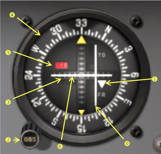
In this next CDI instrument, there are:
0) Course deviation bar (white bar)
1) TO/FROM indicator (and marks)
2) Course select knob (OBS) (omnibearing)
3) Course deviation
4) Compass card (Manually rotation method for CDI)
5) NAV flag warning (NAV and/or GS)
6) Glide scope bar or pointer (not used with VOR)
¶ Horizontal Situation Indicator - HSI
The HSI is an aircraft instrument normally mounted in place of a conventional heading indicator. It combines a heading indicator with a VOR/ILS display.
On the HSI, the aircraft is represented by a schematic figure in the centre of the instrument – the VOR/ILS display is shown in relation to this figure. The heading indicator is usually slaved to a remote compass and the HSI is frequently interconnected with an autopilot capable of following the heading select bug.
In this instrument, there are:
0) Course deviation bar (white bar)
1) TO/FROM indicator
2) Course select knob
3) Course deviation scale
4) Compass card (automatic rotation for HSI with heading)
5) Select course pointer (only for HSI)
6) Symbolic aircraft (only for HSI)
7) Heading select knob (only for HSI)
8) Heading select bug (only for HSI)
9) NAV (or GS) flag warning
10) Lubber line (Orange or white)
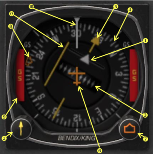
Lubber line represents the current aircraft flying direction.
The HSI illustrated above is a type designed for smaller airplanes and is the size of a standard 3 1⁄4 inch instrument. Airline and jet aircraft HSIs are larger and may include more display elements.
The desired course is selected by rotating the course select knob, in relation to the compass card. The HSI has a fixed aircraft symbol and the course deviation bar displays the aircraft’s position relative to the selected course.
The TO/FROM indicator is a triangular pointer:
- When the indicator points to the head of the course select pointer, the arrow shows the course selected. If properly intercepted and flown, the course will take the aircraft to the chosen facility.
- When the indicator points to the tail of the course, the arrow shows that the course selected, if properly intercepted and flown, will take the aircraft directly away from the chosen facility.
On a conventional VOR indicator, left/right and to/from must be interpreted in the context of the selected course.
When an HSI is tuned to a VOR station,
- Left and right always mean left and right
- TO/FROM is indicated by a simple triangular arrowhead pointing to the VOR. If the arrowhead
points to the same side as the course selector arrow, it means TO, and if it points behind to the side opposite the course selector, it means FROM.
¶ Electronic HSI
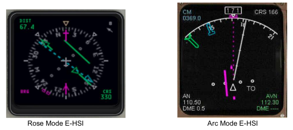
The most modern HSI displays are computed and integrated with electronic flight instrument systems into dedicated instruments or into "glass cockpit" systems.
¶ Radio Magnetic Indicator - RMI
The RMI is a navigational aid providing aircraft magnetic or directional gyro heading and VOR, GPS, and ADF(for NDB) bearing information.
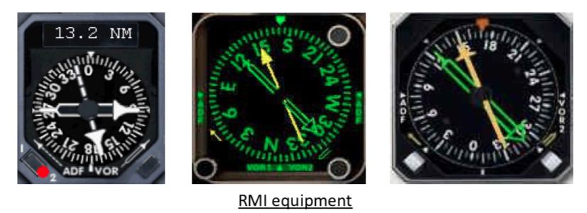
The RMI consists of a compass card, a heading index, one or two bearing pointers, and pointer function switches.
The two pointers are driven by any two combinations of a GPS, an ADF, and/or a VOR.
The pilot has the ability to select the navigation aid to be indicated. In the figure on the right, the RMI is configured to receive 2 VOR, 2 NDB (ADF) or combinations of one VOR and one NDB.
Note that there is no course with the RMI. RMI will work like an ADF.
¶ VOR Frequency selector
The navigation receiver is the control unit where pilots select the VOR frequency.
Usually, many aircraft have 2 navigation receivers named NAV 1 and NAV 2.

These images above show a Beechcraft (at the left), a Cessna (at the centre) and a Boeing (at the right) Selectors.
NAV equipment has its own controls:
- Frequency selector: frequency is tuned by rotating 2 knobs until the wanted frequency is obtained.
One knob for the main digits and another for decimal digits. On the smallest aircraft you can tune
the wanted frequency directly or tune a standby frequency (non-active)
- Band selector on heavier aircraft (Airbus Boeing)
- Mode selector (NAV, DME ...) on light aircraft
- Frequency switch between Active frequency and Standby frequency (only when standby frequency exists)
¶ VOR to determine position of the aircraft
From the radial detection, the aircraft can follow any course passing through the VOR station, either inbound or outbound. Crossing two VOR radials allows the determination of the exact position of an aircraft.
The VOR and VOR/DME beacons are installed to make it possible for an aircraft to fly to or from a VOR beacon at a selected heading.

Reporting points and other significant points are normally established along radials either together with given DME distances from an associated VOR, or by an intersection of radials from two different VORs.
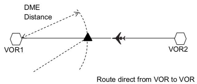
In the previous example and in order to maintain the accuracy of the track flown, the aircraft shall change-over from one VOR to another at the mid-point between the two VORs concerned.
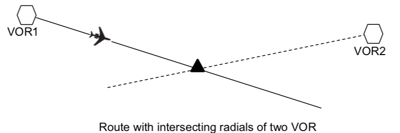
In the previous example, the aircraft will use VOR1 for maintaining the route. The VOR2 will be used as reference information to find the intersecting fix.

In the previous example, the aircraft will use the VOR2 as reference information in order to determine or confirm its location.
- VHF Omnidirectional Range - VOR (Beacon)
- [Horizontal Situation Indicator - HSI](
- Course Deviation Indicator - CDI
- None
- VID 150259 - Creation
- VID 450012 - Update
- VID 496402 - Wiki.js integration