¶ Introduction
This document is created to help you with some useful functions for advanced users in Aurora, which will help you improve your experience while using the software.
The tips that are given here require knowledge of Aurora. If you don't understand some terms, please refer to the ATC Client Aurora Manual.
¶ Static Label Editor
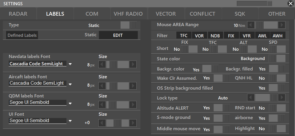
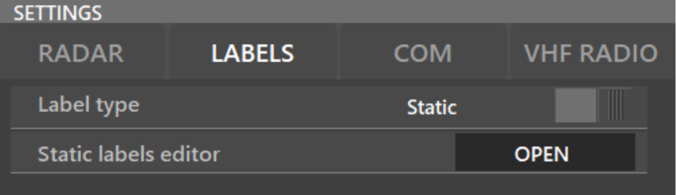
To activate the label editor, go to PVD → SETTINGS → LABELS, choose label type from DYNAMIC (that is the standard label) to the STATIC that is the editable one. After that, to customize them, choose OPEN on Static Label Editor
¶ Label editor:
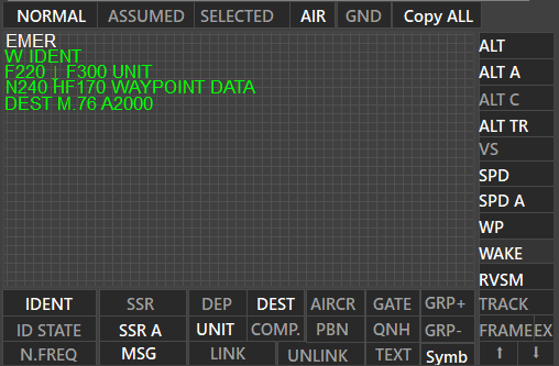
On the label editor, there are three situations: NORMAL, ASSUMED and SELECTED. On each one, you have the options to activate all types of labels, such as:
¶ Button Definition
¶ Horizontal Bar Buttons
- IDENT – Traffic callsign
- SSR – active SSR (it will show the SSR code of the aircraft regardless of the identification state)
- DEP – FPL Departure
- DEST – FPL destination
- AIRCR – Aircraft ICAO code
- GATE – Assigned Gate
- GRP – Lets you alternate the field selected every 2 seconds. See information below
- ID STATE – state around IDENT (regarding departure or arrival colorschemes)
- SSR A – assigned SSR
- UNIT – which ATC is the traffic with
- COMP – company
- PBN – Displays the defined label depending whether the AC has PBN capabilities
- QNH – Shows the QNH of the DEST or ARR airport of the aircraft
- N.FREQ – display the selected next ATC frequency (will only work on assumed/selected states)
- MSG – messages such as CA, IDENT, and others
- LINK / UNLINK – Links or unlinks multiple fields
- TEXT – free text area, to do any types of personal notes. The text written here will be transferred to the adjacent ATC when the traffic is transferred
- VS Symb – (VS Symbol) shows arrow of climbing and descending (symbol editable by editing profile)
QRP Use Case
As you can see, every few seconds the labels alternate when defined as + or - when selecting a field and using QRP.
¶ Vertical Bar Buttons
- ALT – current traffic altitude
- ALT A – cleared altitude
- ALT C – FPL altitude
- ALT TR – stands for Transfer Altitude, which means the level at which you will transfer the traffic to the next ATC
- VS – vertical speed
- SPD – current speed in GS
- SPD A – assigned speed
- WAKE – wake turbulence of the aircraft
- RVSM – RVSM status
- TRACK – Shows the AC track
- FRAME – STRIP boundaries. Activating it will show the boundaries.
- EX – Frame on Mouse Area
¶ Label Editor
¶ Precission Movement & Special Features
You may change the label positions by moving with the mouse or with precision, by right-clicking on the label and moving it.
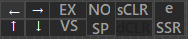
By right clicking it, you will also see the following options:
- EX – Makes the field visible under the Mouse Area
- VS – Switches between symbols
- NO SP – Stands for NO SPace after the selected field
- sCLR – Lets you select an special CoLoR for the selected field
- eSSR – Allows you to hide a specific label if a trafficmatch a rule defined in SQK custom settings. Refer to CUSTOM SQK mode
¶ Frame Options
Regarding FRAME, there are some options:

You can edit the label boundaries as it says.
¶ Defined Labels
When having a traffic assumed, Defined Labels will show these information if active:
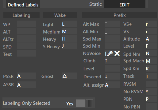
By doing this, you can name what will the labels be named
E.g. Instead of showing wpt, you can change to hdg for example, changing the name on the label itself and so on.
¶ Suggestions
To allow dynamic moving on STATIC labelling and to make them be on the same line, use LINK. That will keep labels aligned. To do that, click on the first label that will be the reference label, then click on LINK and select the following labels that will be on their right. To unlink all labels, just click UNLINK and select the group of labels that were linked.
The same process works for GND, which represents the labels for ground traffic. To copy the currently selected type of label to all others (NORMAL, ASSUMED, OR SELECTED), for example, copy NORMAL to ASSUMED and SELECTED on AIR, click on Copy ALL. Same thing on GND

¶ FLTR - Traffic Filter
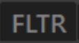
This function allows to filter traffic separatelly on the PSR or SSR depending if the traffic is an inbound or an outbound.
To configure this filter you have to press SHIFT when clicking the FLTR button; the following window will appear:
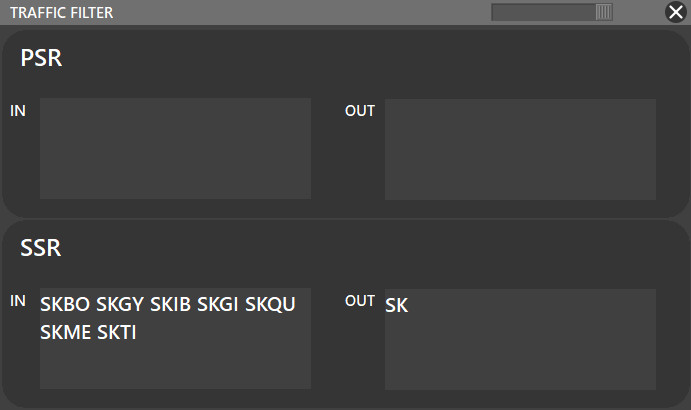
As you can see there is not any filter for the PSR, only for the SSR. In this case scenario, the SSR radar will only display traffics INBOUND: SKBO, SKGY, SKIB, SKGI, SKME, SKTI; and all the traffics OUTBOUND ==SK== airports. Chek this Wikipedia Article about ICAO country codes.
¶ LIST - Traffic Lists

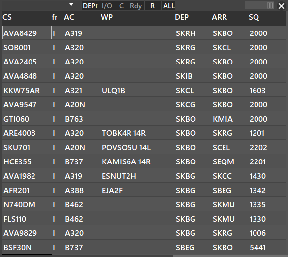
List function allows the user to display custom lists as shown:
¶ Traffic List Structure Manager Window
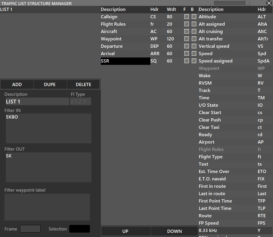
To set up LISTs in Aurora SHIFT + Click the LIST button. Then, the following window will appear:
For an easier understanding, we divided the lists into 3 columns:
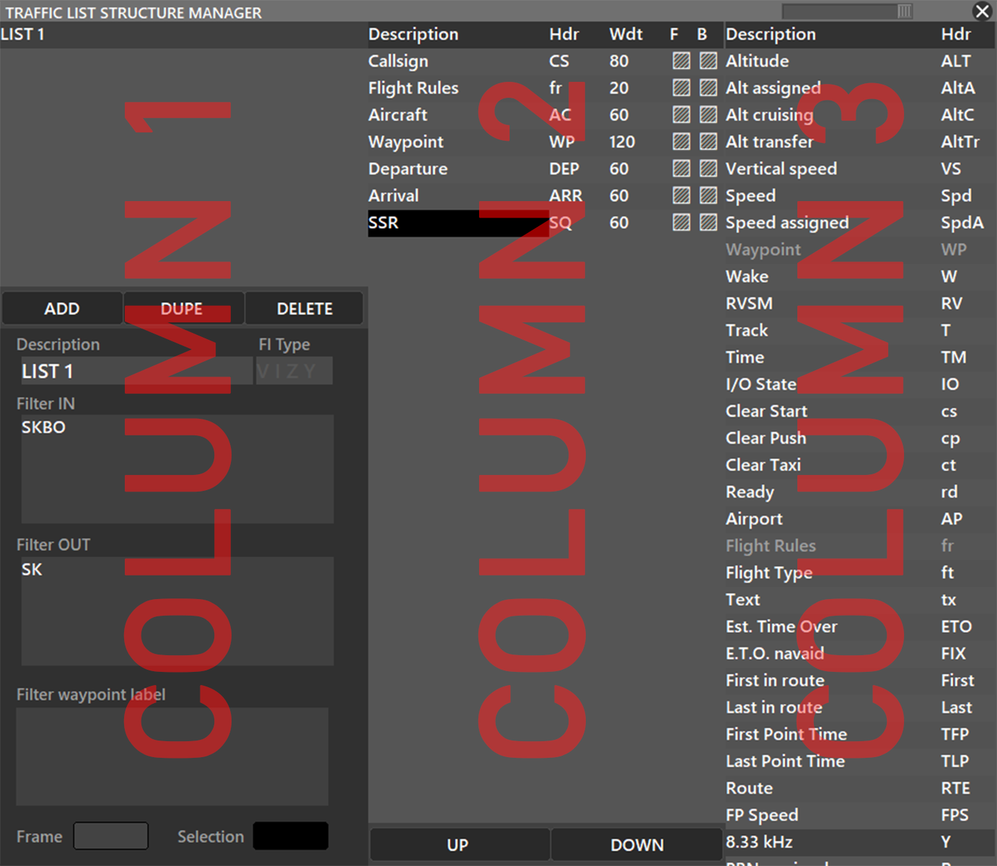
¶ Column 1
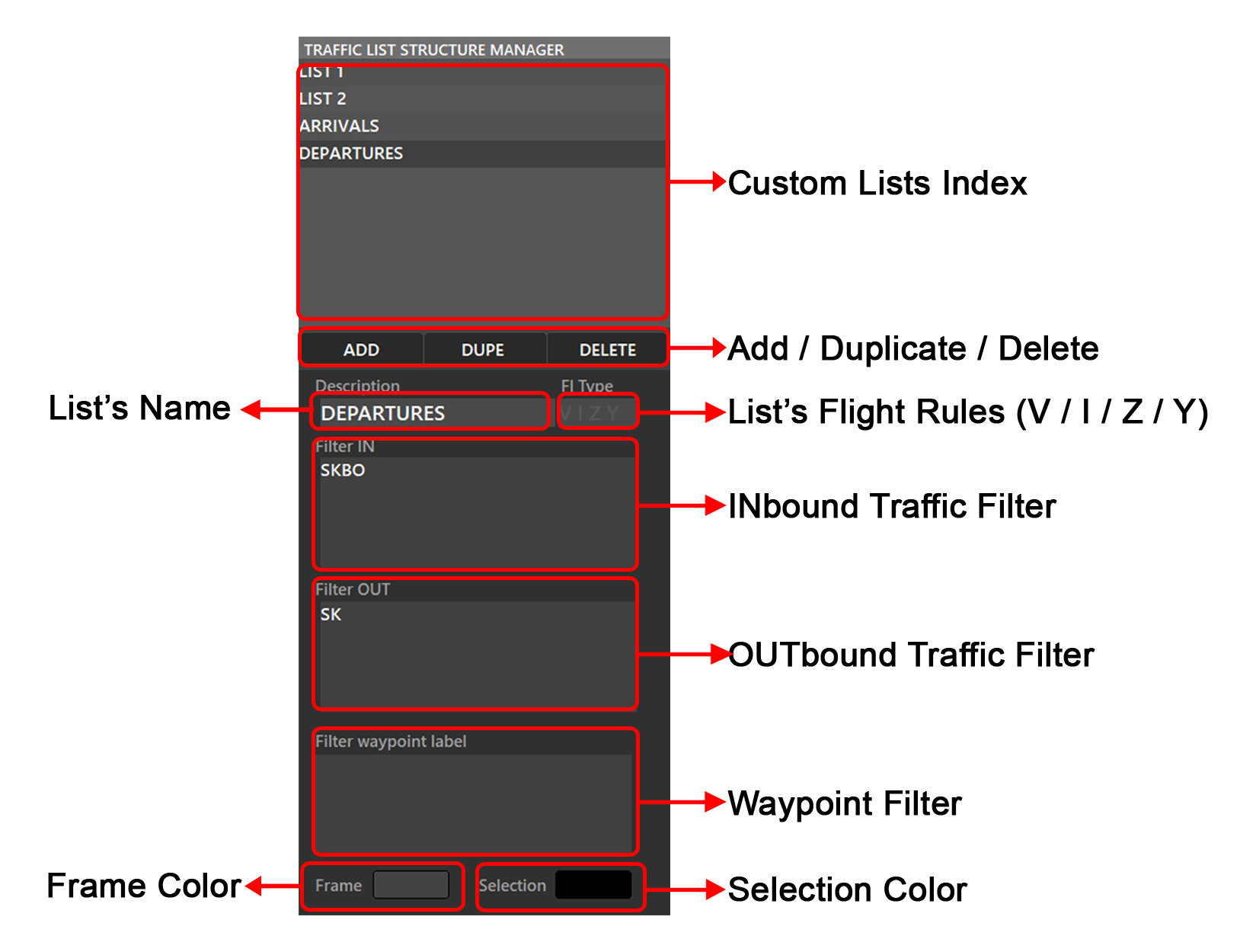
- ADD / DUPE / DELETE : Adds, duplicates, or deletes the selected list
- List Description : Names the selected list
- Fl Type : (Optional) Will show in the list only flights with a V, I, Z or Y flight plans
- Filter IN : Will filter INbound traffics using ICAO airport codes. Refer to
FLTRfunction above. - Filter OUT : Will filter INbound traffics using ICAO airport codes.
- Filter Waypoint Label : Will filter traffics by using waypoints
- Frame Color : Color of the outline of the lists window (By default is Aurora's Gray)
- Selection Color : Color of the selected cell in the list.
¶ Column 2
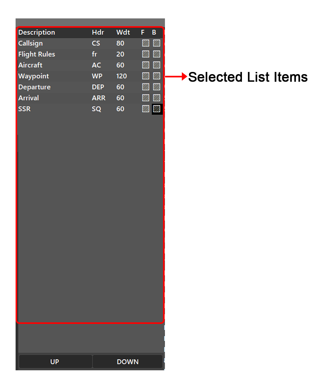
Shows the list's current fields
- To add one field from the list use the 3rd column, and double click the field you want to add
- To remove one field from the list double click the field's name you want to remove on the 2nd column. E.g. If you want to remove the Aircraft field, double click the Aircraft cell to remove it.
- To change the Column Header double click the Hdr (such as CS, fr, AC, WP) of the field you want to modify and then type the new one
- To change the Column Width double click the Wdt (in pixels) of the field you want to modify and then type the new one
- To change colors:
- Text's Color: Use the F column in the editor to change the color of the actual text
- Backround Cell Color: Use the B column in the editor to change the color of the text's backround
¶ Column 3
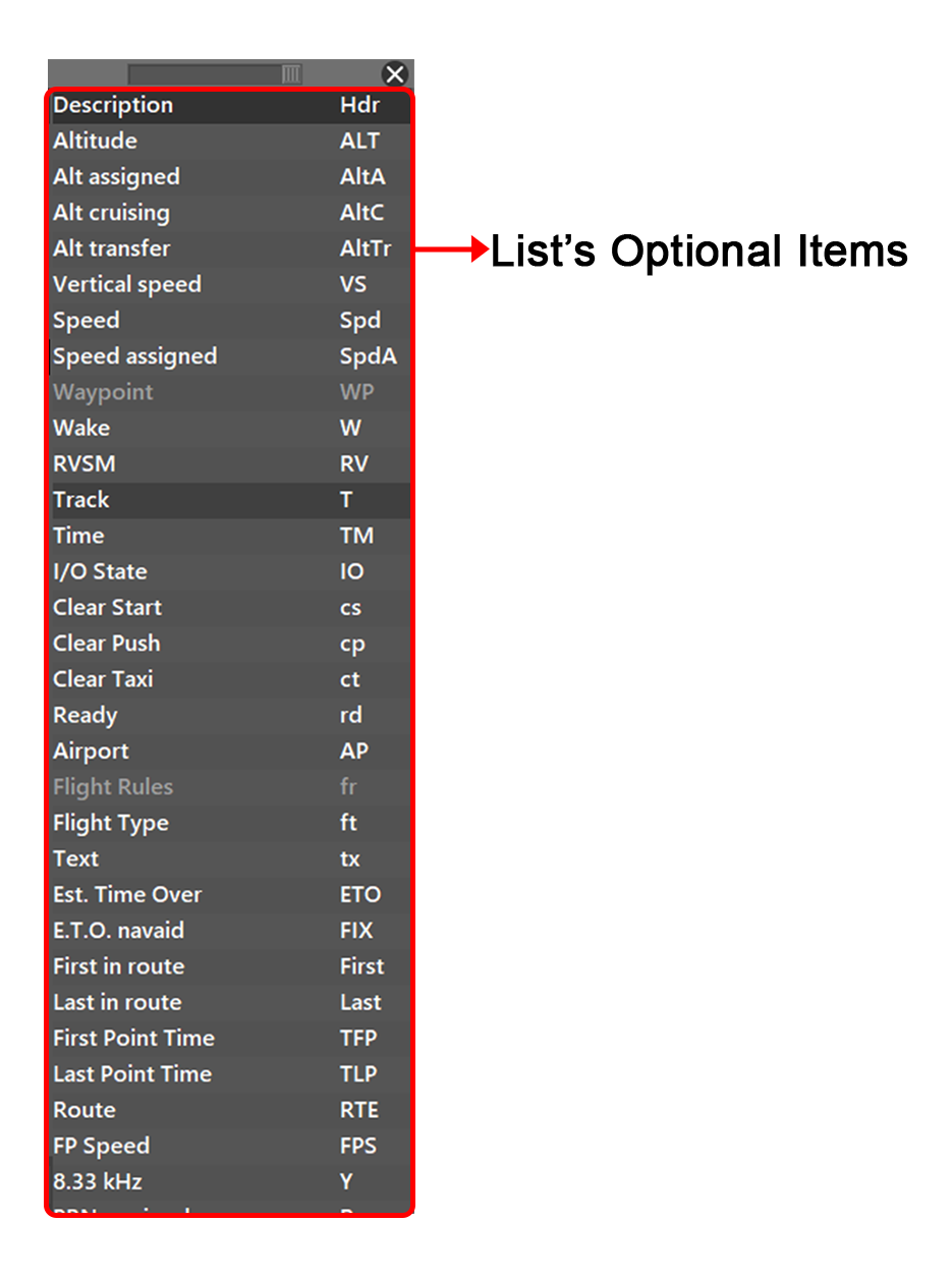
Shows the available items you can add to the lists. To add an item into the list double click the field in question.
¶ How to create a new list?
- To create a new list first name your new list, in the picture, the list is named as LIST 1
- Then, (Optional) you can specify the flight rules for that list. Select between Y, Z, I, V flight rules.
- Filters (Optional), if you want to add filters by selecting the airport ICAOs or the country ICAO codes on their respective INbound and OUTbound fields.
- You can customize the color of the frame or the color of the selected field at the bottom-right corner of the window.
- Using the 3rd column, select the fields you want to add to the list
- Click ADD and you will have your list ready to be used when clicking the LIST button
¶ Custom Symbols
First, to access this menu you have to go to PVD SYMBOLS.
==Coming soon...==
¶ Custom SQK mode
First, to access this menu you have to go to PVD SQK Select: CUSTOM.
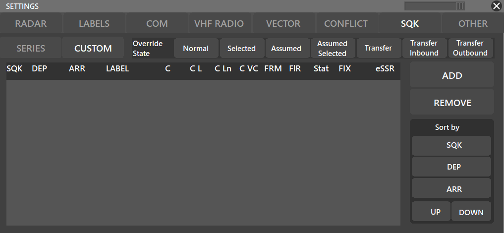
==Coming soon...==
¶ QDM
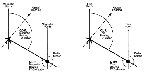
¶ What is QDM?
As stated in the IVAO's “Introduction to navigation” document:
- QDM: Magnetic Bearing TO the station (from the aircraft)
¶ How is it used?
There are several different ways to use QDM and each serves a different purpose.
You can use the QDM tool from both an aircraft or a specific location on the radar screen. To bring up the tool:
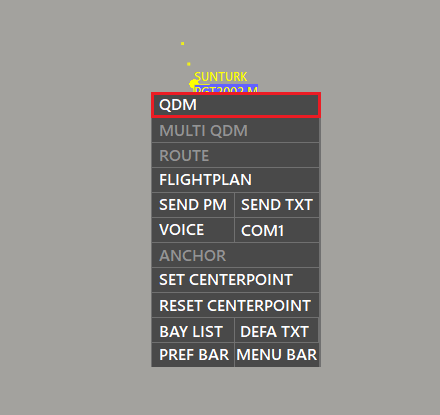
- Double click to the aircraft/location or,
- Right-click to the aircraft/location and select QDM
After activating the QDM, you will see a white line that will follow your mouse cursor.
You can change the color of the line from the settings, too. For further information please refer to our ATC Client Aurora Manual
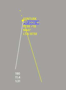
You can move the tool by simply moving your mouse. There are three lines at the end of the tool, and each represents different information:
- Magnetic bearing to the station
- Distance to the station
- The estimated time when the aircraft will arrive
When you are done with the QDM, again double-click to the aircraft/radar, right-click and de-select the QDM, or hold SHIFT while moving the mouse cursor.
¶ Moving the QDM
You can move the QDM you have created for an aircraft to another aircraft. In order to do that, move your mouse cursor to the texts at the end of the QDM and click them.
Then, you will see the square becomes red. Now, click on the other traffic which you want to move the QDM.
¶ Set QDM Heading into the WP Label
First, to set how much you want to round the QDM heading when using this feature, you have to go to PVD OTHER Assign Heading from QDM (and set your preffered value).
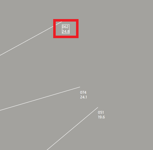
This funtion allows you to click the QDM heading inside the QDM box, to automatically set that heading into the WP label of the traffic in question. As shown here:
As the image shows, a red box highlights the heading in the QDM box, when you click it, it will assign that heading to the WP Label. In the image, the previous label was OSUS4R 14L which was changed to H065.
¶ Multi QDM
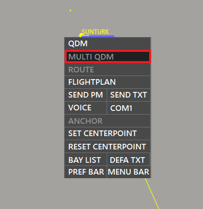
You can use multiple QDMs at the same time. In order to activate the Multi QDM option, right-click to any point on the radar screen, then select “MULTI QDM”, make sure its color is changed to white.
After the Multi QDM is activated, you can use more than one QDMs at the same time by creating QDMs like you were used to.
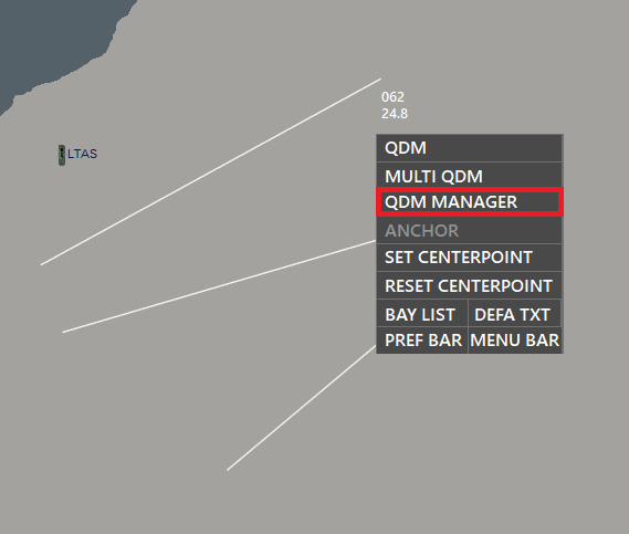
When the Multi QDM is activated, you will see the QDM Manager come up when you right-click to the radar.
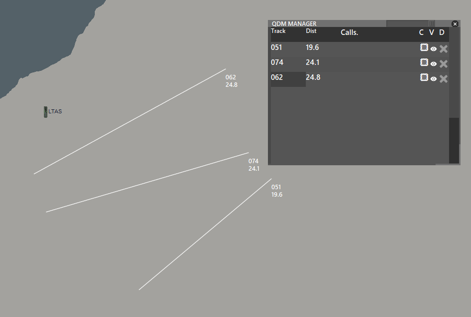
There, you can remove a single QDM, hide, or change its color.
But, there is a more practical way to remove a single QDM. Move your cursor to the texts at the end of the line.
A square will appear over your cursor, double-click the square, and the QDM will be removed.
To remove all the QDMs and deactivate the function, right-click again and de-select the MULTI QDM
¶ QDM with Turn Calculation
There is a feature that takes traffic response time and turning rate/speed/time into the calculation and displays the proper magnetic bearing.
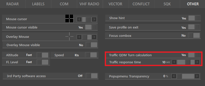
You can activate it by navigating to Settings (F7). Below the “OTHER” menu, you will see two options:
- Traffic QDM Turn calculation: By turning this to “Yes” it will become activated.
- Traffic response time: You can adjust the response time of the traffic and get more accurate bearings.
After you are done with these two settings, go back to the radar screen and use the QDM tool as it's used normally.
You will notice a different QDM line when compared to “Turn Calculation NO".
The most effective way to use the turn calculation is, first, create the QDM from the traffic, then put your cursor to the point where you want the aircraft should arrive.
¶ Bay List
Bay List can be used to make requests to the adjacent ATC units. With help of the Bay List, you can do, but not limited to, the following:
- If an aircraft will enter your control area, you can request from the adjacent ATC unit to send it to a specific waypoint, transfer it to you at a specific flight level, or with speed restrictions.
- If an aircraft will leave your control area, the next ATC can request from you the same,
- You can request him for permission to give instructions that are not in your control zone. For example, if a waypoint is not in your area, but if you ask the ATC through the Bay, you can give the traffic direct to that waypoint.
¶ The logic behind the Bay List
- Firstly, there has to be an offer, we define this as Bay Request. You should first make a request to the adjacent ATC unit.
- After that, the ATC that you have sent the Bay Request will review your offer.
- Then, the ATC will have three options, modify it and send it back, accept it, and deny it.
- If the Bay Request is denied, you can send another one.
- If the ATC modifies it and sends it back to you, then you have again two options; modify it and send it back, or accept it. If you accept it, it means there is no further thing to discuss. If you modify it and send it back, you will go back to step two.
- If the ATC accepts the request, then it means there is no further thing to discuss and execute your request.
¶ If the aircraft is assumed to you
If the aircraft is assumed to you, to send a Bay Request to the adjacent ATC unit, right-click to the traffic, and your usual Transfer menu will come up. Now, you can see there are 3 columns. The plane symbol below the “B” column means Bay. To send a Bay Request, press the symbol in the row of the relevant ATC unit.
On this screen, you will see the following things, from left to right:
- White double arrows mean the Bay is not sent yet.
- Arrow to the top right corner means you are sending the Bay request.
- To delete the Bay Request, double-click to the trash bin
- The fourth and fifth information is the ATC unit which the Bay sent to and the callsign of the aircraft.
- The next two fields are left for you to fill. You can type a waypoint/flight level/speed/arrival information or any other thing you want to write to the adjacent ATC unit.
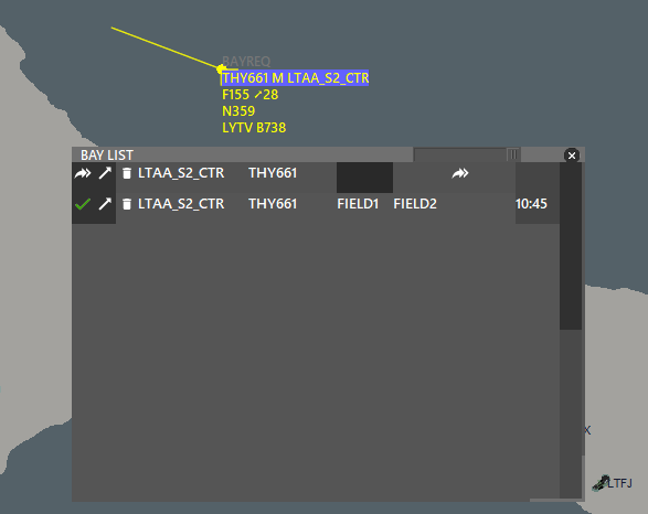
- If you press the second white double arrow, it will send your request to the relevant ATC unit.
After sending the request, the first double arrows will become blue, which means you have sent it, and the timestamp on the right shows the time you have sent the Bay Request.

If the ATC you have sent the bay, accepts your request, you will see a green checkmark.
If your request is denied or modified and sent back to you, then you will return to the first step.
¶ If the aircraft is not assumed to you
In such a case, there are two possibilities:
¶ Requesting Bay from the responsible ATC
To make a Bay Request to the ATC who is controlling the traffic, right-click to the aircraft and select “BAY LIST”
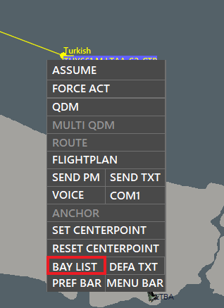
This will bring up the menu which you already saw in the section above.
Again, you can fill the fields and send the request to the responsible ATC unit.
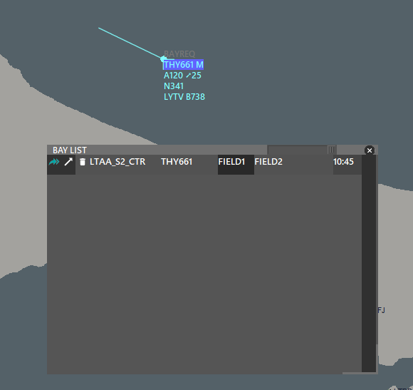
¶ Responsible ATC requesting Bay from you
The responsible ATC unit can also make a Bay Request to you.
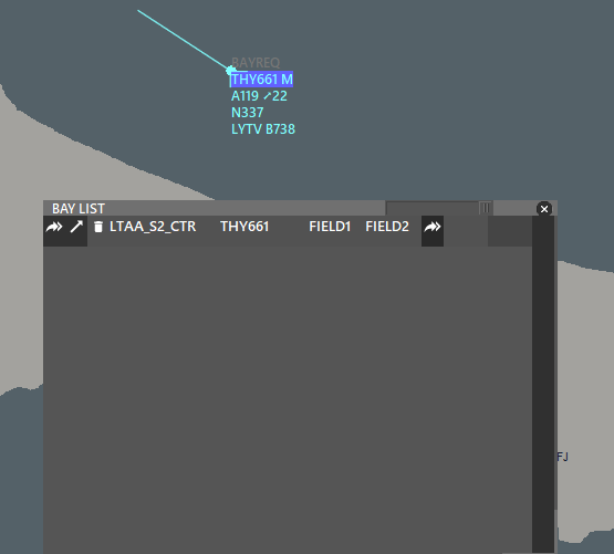
When you receive the request, you should see “BAYREQ” over the traffic and hear “Incoming Bay”, if it is enabled from the sound settings. For further information, please refer to our ATC Client Aurora Manual
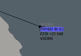
You can change the color of the text “BAYREQ” from the color settings.
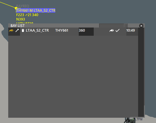
When you receive the Bay Request, the menu will be the same with few differences:
- The Orange double arrow means this is an incoming bay.
- You can either modify it and send it back to the relevant ATC by pressing white double arrows or accept it by pressing a white checkmark.
¶ Using Bay List with on-screen strip
If the on-screen strip is enabled, you can also make Bay Requests from there.
The working logic is the same as the list, you can type anything you want into two blank fields and send it to the adjacent ATC unit.
But, keep in mind that Bay from on-screen strip can be used only in two conditions:
- If you have assumed the traffic and selected a “Next ATC”. This will send the request to the ATC you selected next. If you don't know what that means, please refer to the next section.
- If you haven't assumed the traffic and to make a request from the responsible ATC unit.
¶ Next ATC
Selecting the next ATC will make your job easier when transferring the traffic to the adjacent ATC unit.
When you right-click an aircraft to transfer, you will see the available ATCs to transfer. However, this can be confusing and hard to find when there are many adjacent ATC units. As a solution, you can select the Next ATC and when you transfer the traffic, you will only see the ATC you have chosen before.
![]()
To select the Next ATC, press the “WiFi Symbol" in the N column of the relevant ATC.
After pressing it, the transfer list should be shown like below:
![]()
To transfer the traffic to the adjacent ATC unit, just press the newly opened name under the “Transfer/Bay”. Don't worry, despite it is being shown over the “Release”, it will not send the traffic to the Unicom, but to the next ATC unit.
The ATC unit which you selected, will also see the traffic in a different color (which can be edited from the Colors settings).
![]()
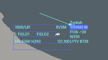
¶ On-screen strip
If you select a “Next ATC”, you will also be able to see the ATC's both callsign and frequency from the on-screen strip. For further information about the on-screen strip, please refer to our ATC Client Aurora Manual
![]()
¶ VERA
VERA is a tool that can be used to predict conflicts and preventing them. When it is used properly, the VERA has great importance to Approach/Enroute Controller
¶ How to use VERA?
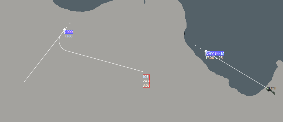
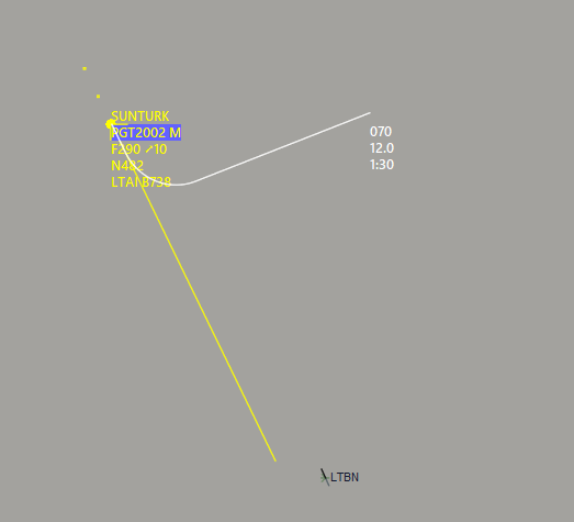
Normally, when you create a QDM from aircraft and place it on another aircraft, you will see something like the below:
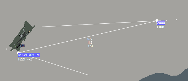
Over the QDM line, there are three information displayed:
- The first line shows the magnetic bearing from the selected aircraft to the other aircraft as it is in the QDM. Keep in mind that it shows the bearing from the first selected aircraft (QDM created aircraft) to the second selected aircraft (QDM placed aircraft)
- The second line shows the distance between two aircraft
- The third line shows the time two aircraft will become the closest.
This line and pieces of information are the most basic things that you will need. But you can get more information about conflicts and prevent them by using VERA tool. To activate it, press the VERA on the PREF BAR and make sure if its color changed to white.

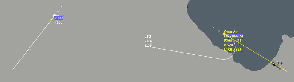
After enabling the VERA, doing the same steps above will bring different lines and information:
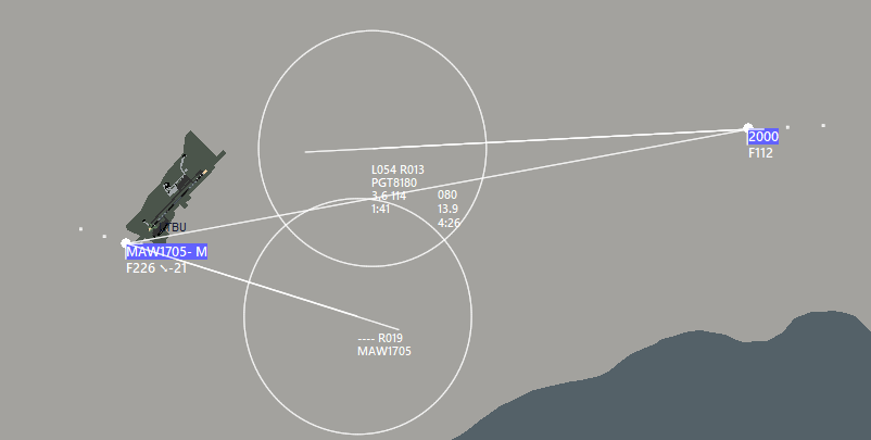
The middle line (QDM) remains the same, but the others are new (VERA lines). They each represent different information.
There can be differences in information which are shown, depending on:
- Aircraft's altitude
- Aircraft's heading
- Two aircrafts' positions to each other.
Now, let's take a look at the information which is shown over our VERA line:

- In the first line, it gives suggested headings to avoid conflict. In our case, it suggests the traffic PGT8180 to turn whether left heading 054 or right heading 013 to avoid the collision.
- The second line shows the aircraft's callsign
- In the third lane, there are two pieces of information. The first one is the distance, which two aircraft will become the closest. So, in our case, two traffics will become a maximum of 3.6 miles close to each other. The second given information is the altitude difference, written in Flight Leve.
- The fourth, and the last line shows the remaining time to the point where two aircraft will become the closest.
¶ When using the VERA, please keep in mind that:
- The information shown when using the VERA tool is dependent on your conflict settings. You can change your conflict settings to adjust your VERA tool as well. Please refer to our ATC Client Aurora Manual to learn how to do it.
- The VERA tool will not work if there are more than 30 minutes between the two aircraft.
- Some lines/information may be missing because the conflict will not happen or there are not suitable recommendations.
¶ DEFA
DEFA is a tool that can be used to define temporary areas. The usage areas for DEFA maybe, but are not limited to, the following:
- To mark a specific location that has turbulent weather or other significant weather changes.
- To see some altitude information regarding MSA, MRVA, MORA, etc. which are not present in the sectorfile.
- To mark dangerous/restricted/prohibited areas/NOTAMs which are not defined in the sectorfile.
¶ How to use DEFA?
There are two ways to use the DEFA tool:
¶ Defining a specific point
To define a specific point, right-click to the point where you want to define and select “DEFA TXT”.
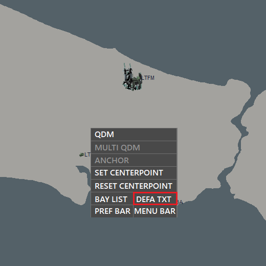
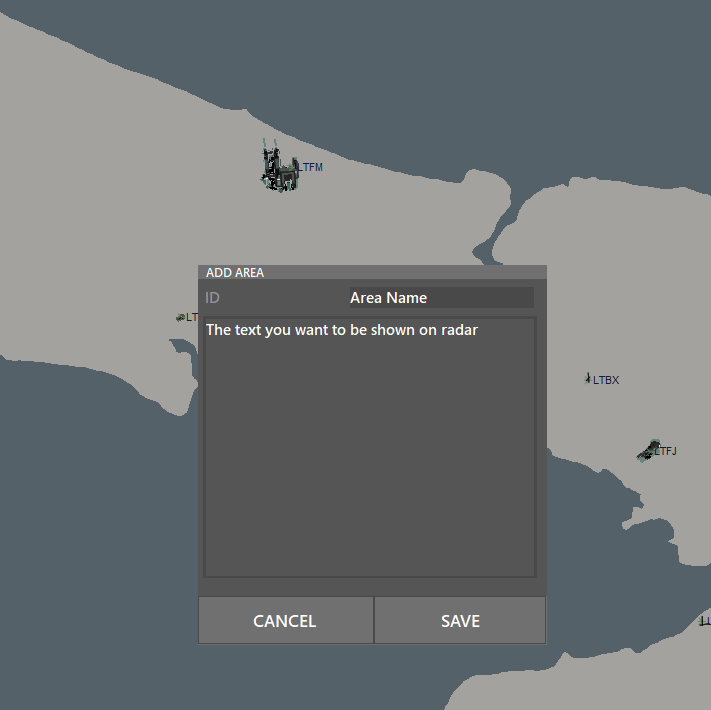
After that, a small window will be opened and you have to make two entries:
- ID: Name of the defined area, which is only you will see.
- The text: What you want to see on the radar screen.
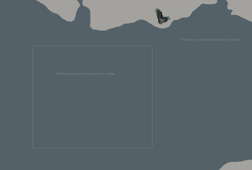
After filling those two fields, then the text will be visible to you at where you first right-clicked on the radar.

¶ Defining an area
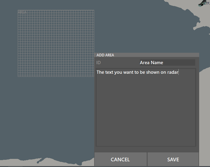
To define an area, navigate to the PREF BAR and click DEFA. Make sure that it is shown white instead of grey.

Then, select the area you want to define while holding the middle mouse button. So, you should see something like this:

When you selected the area, release the middle mouse button and you will see the same menu that you saw while defining a certain point:
- ID: Name of the defined area, which is only you will see.
- The text: What you want to see on the radar screen.
After pressing SAVE, the text you have written will follow your cursor. To place it, click on somewhere you want it to be shown.
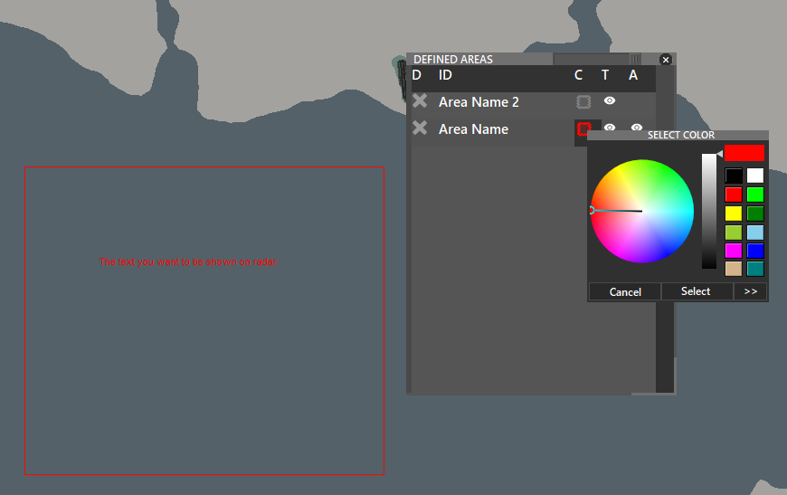
¶ Editing the area
To edit or hide the area you defined, navigate to the PREF BAR and SHIFT + Click DEFA
You will see a window that you can do the following things:
- Change color: Under the column “C”, press the relevant symbol of the area which you want to change its color.
- Hide/Show the defined text: Under the column “T”, you can hide or show the text you defined by pressing the relevant eye icon.
- Hide/Show the defined area: Under the column “A”, you can hide or show the text you defined by pressing the relevant eye icon.
¶ Anchor
Anchor is a tool that can be used to measure the remaining time of an aircraft to a given point.
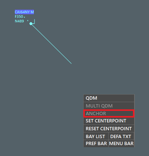
The most useful time to use the Anchor is: If a group of aircraft is inbound to the same fix from the same direction, you may set the Anchor at the certain fix and learn the remaining time to that fix for each aircraft by clicking on them.
To activate and set the anchor, right-click on the main radar screen and press “ANCHOR”
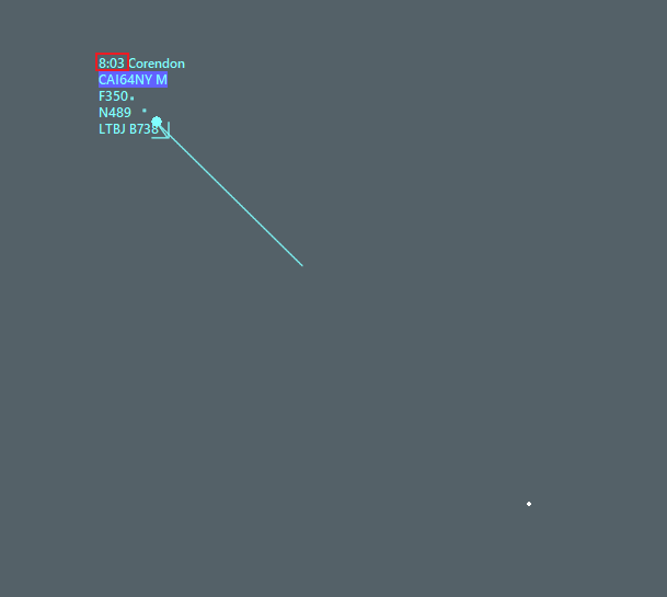
To see the aircraft's remaining time to the Anchor, make sure that the aircraft is assumed and selected.
You will see the time information next to the company information.
When the Anchor is set, you may right-click and set the Anchor somewhere else, by selecting “SET ANCHOR”, or remove it entirely by selecting “ANCHOR”
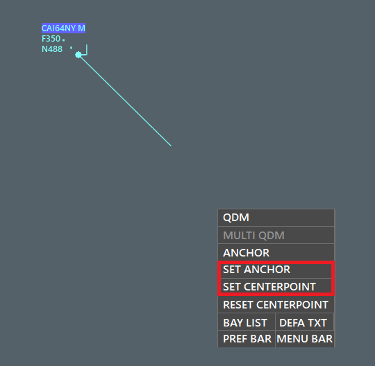
Additionally, the information regarding the centerpoint distance and location will change to Anchors centerpoint distance and location.
¶ Shortcuts
Currently, Aurora has the following functional shortcuts:
-
F1 : Open Sector Definition List
-
F2 : Reset Zoom place to profile's saved zoom
-
F3 : Supervisor module
-
F4 : Save Profile
-
F5 : Open Colorscheme editor
-
F6 : Open Soundscheme editor
-
F7 : Open Settings editor
-
F8 : Show Flightplan window
-
+ / - : Zoom in / out
-
z : Assume/Release (selected label)
-
q : Request SSR Code
-
w : Add Waypoint (selected label)
-
a : Add Altitude (selected label)
-
s : Add Speed (selected label)
-
t : Transfer (selected label)
-
x : Send Text (selected label)
-
CTRL + I : INSET Bar
-
CTRL + T : TRAFFIC Bar
-
CTRL + G : GEO Bar
-
CTRL + N : NAV Bar
-
CTRL + Q : Show / Hide VOR's
-
CTRL + W : Show / Hide NDB's
-
CTRL + E : Show / Hide Fixes
-
CTRL + F : Show / Hide Frequencies
-
CTRL + V : Show / Hide VFR Fixes
-
CTRL + SHIFT + V : Show / Hide VFR Route
-
CTRL + M : Show / Hide MRVA
-
CTRL + H : Show / Hide High Airway
-
CTRL + L : Show / Hide Low Airway
-
CTRL + S : Show / Hide All Labels
-
CTRL + R : Show / Hide Range Rings
-
CTRL + T : Show / Hide Vectoring T
-
CTRL + X : Show / Hide Mouse Area
-
CTRL + A : Show / Hide Aiports
-
CTRL + SHIFT + C : Show / Hide Coastlines
-
CTRL + SHIFT + D : Show / Hide Gates
-
ALT + A : Show / Hide ATC Online
-
ALT + Q : Show / Hide Danger Areas
-
ALT + W : Show / Hide Prohibited Areas
-
ALT + E : Show / Hide Restricted Areas
-
CTRL + 1 : Open INSET 1
-
CTRL + SHIFT + 1: Open INSET 1 at Main Screen Zoom level
-
CTRL + 2 : Open INSET 2
-
CTRL + SHIFT + 2: Open INSET 2 at Main Screen Zoom level
-
CTRL + 3 : Open INSET 3
-
CTRL + SHIFT + 3: Open INSET 3 at Main Screen Zoom level
-
CTRL + 4 : Open INSET 4
-
CTRL + SHIFT + 4: Open INSET 4 at Main Screen Zoom level
-
CTRL + 5 : Open INSET 5
-
CTRL + SHIFT + 5: Open INSET 5 at Main Screen Zoom level
-
CTRL + 6 : Open INSET 6
-
CTRL + SHIFT + 6: Open INSET 6 at Main Screen Zoom level
-
CTRL + 7 : Open INSET 7
-
CTRL + SHIFT + 7: Open INSET 7 at Main Screen Zoom level
-
CTRL + 8 : Open INSET 8
-
CTRL + SHIFT + 8: Open INSET 8 at Main Screen Zoom level
¶ COMBOX Shortcuts
- .c : Find navaids and airports
- .t : Find traffic
- .wx ICAO : Receive METAR
- .taf ICAO : Receive TAF
¶ Author
- VID 545587 - Creation
- VID 657678 - Reformatting and Updates