¶ Introduction
This document will describe the IVAO Pilot Software: Altitude version 1.11.0b and above with Voice Integration and Voice ATIS.
The Pilot Client software is composed of two software components and needs one Web application:
There are
- Altitude Pilot Core
- Altitude User Interface (UI) application
- Flight Plan System Web application
¶ Connector Software (Pilot Core)
Altitude is compatible with the following simulators:
- a 32bit DLL file for Microsoft Flight Simulator 2004 (FS9)
- a 32bit DLL file for Microsoft Flight Simulator X and Steam Edition (FSX, FSX:SE)
- a 64bit DLL file for Microsoft Flight Simulator
- a 32bit DLL file for Lockheed Martin P3D V1, V2 and V3
- a 64bit DLL file for Lockheed Martin P3D V4 and V5
- a 32bit XPL file for the Laminar Research Flight Simulators : X-Plane 9 & 10 - 32bits
- a 64bit XPL file for the Laminar Research Flight Simulators : X-Plane 10 & 11 & 12 - 64bits
The connector (CONN) is the file installed inside your flight simulator that reads and writes flight data of your simulator. It also enables local network Ethernet connection to allow access to these data by the User Interface (UI).
The connector (CONN) also handles communication with IVAO SHARD servers to:
- send aircraft position to the server
- receive other user aircraft positions to display MTL/CSL inside your simulator
- receive and transmit communication text with other Pilots and ATC
- server information exchange (system messages, answers to pilot text requests, ...)
Microsoft Flight Simulator 2002 is not compatible with the current version of the Altitude Client.
¶ User Interface (Pilot UI)
The User Interface (Pilot UI) is an application which runs outside the flight simulator in your operating system.
It manages the connection with the Pilot Core connected directly on the same computer or a computer connected via an internal Ethernet network.
The user Interface (UI) can be run on:
- All 64 and 32bit versions of Microsoft Windows
- Mac OSX 10.6 and above
- Linux 64bit
The User Interface (UI) main features are:
- Display text communication with other IVAO users
- Voice plugin
- Manage Private Communication
- Ease your Unicom communication with Auto Unicom feature
- Manage transponder code and mode
- Display ATC connected around your position
- Retrieve ATIS
- Retrieve and Display Weather information
- Give the possibility to have own TCAS
- Display UTC time
¶ Flight Plan System
The Flight Plan System is a web application that manages all your flight plans for all your flights in IVAO.
The flight plan system main features are:
- create your flight plan from scratch
- modify an existing one
- retrieve and old flight plan from your history
- manage your preferred aircraft in a virtual hangar
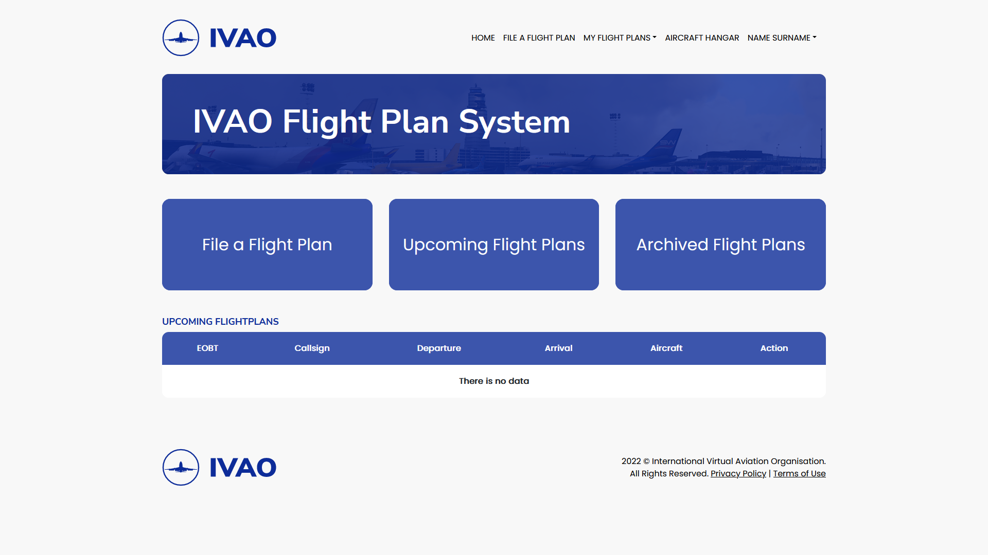
Please consult to the documentation of Flight Plan System to learn more!
¶ MSFS Specific Information
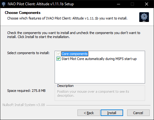
Pilot Core will launch automatically with all simulators except MSFS. For MSFS, you have the option to launch the core on startup while installing Altitude.
If you have not selected this option, you may use the Desktop shortcut for Pilot Core to launch the Core. This option is only available for MSFS.
You may check if the Core is running by checking your Tray Applications. These applications are accesible using the upward arrow symbol on the bottom right of your screen.
¶ Launching Altitude
First, start your simulator and place your aircraft on ground on an airfield or a seaport ( for float aircraft).
When your simulator is running and your aircraft is loaded and waiting, start the User Interface using the desktop shortcut or:
- Windows: launch pilot_ui/win/64/PilotUI.exe
- Windows MSFS Core: \IVAO\PilotCore\pilot_core_fs2020.exe
- MacOS: mount pilot_ui/osx/PilotUI.dmg and start PilotUI.app
- Linux: launch pilot_ui/lin/PilotUI
At the application launch, Altitude will show the connection window. You may not see this window if Altitude automatically detected your simulator. Press Connect to establish the connection between the Core.
- IP Address = 127.0.0.1, if you are running both the UI and the simulator on the same computer, OR the IP of the computer on which flight simulator is running
- Password = ivao (lowercase only; do not use uppercase IVAO)
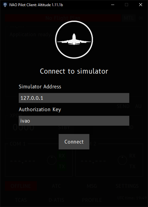
If you return to the same screen after pressing the Connect button, this might mean that the Pilot Core is not installed correctly or it's not running. If you're using MSFS, you should start the Core manually.
If you're running the UI on another device in your local network. You should use the local IP address of the device running the Flight Simulator.
Once connection is established with your simulator. Altitude will ask you to sign into your IVAO account.
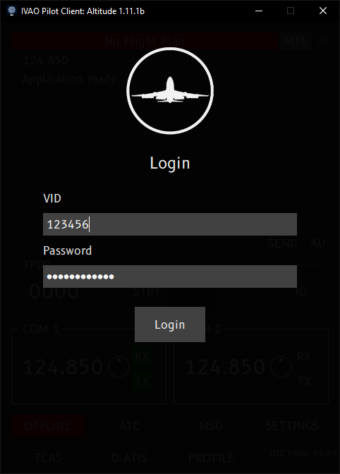
Use your VID and Website Password to login.
For MSFS, do not forget to close the Pilot Core after closing the PilotUI. You should run Pilot Core again before running the Pilot UI.
¶ Altitude Main Display
The User Interface is purposely minimal and is broken down in the following major sections:
- Top bar which includes Flight Plan check area, MTL selection button and the pin buttton
- Communication Area
- Input text scratch pad and the Auto Unicom feature
- Transponder panel
- Radio panel
- Action button panel which includes the connection, TCAS, ATIS and settings area
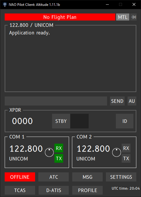
If the pilot UI COM1 and COM2 frequencies are set to ---.--- (see image below), this means that:
- The UI is not connected to the CONN application running in your simulator, OR
- The UI may be connected to a cold and dark aircraft

¶ Top Section
The Top bar contains 3 functions:
- Flight Plan
- MTL Selection
- Pin button
¶ Flight Plan
Flight Plan area's purpose is to display the active flight plan received from the Flight Plan Server.
By default without a flight plan or before any connection, the Flight Plan checking panel will display the default text “No Flight Plan” against a red coloured background.

When you click on this banner, the UI (User Interface) will display the default message:
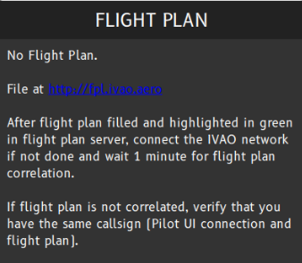
After succesful retrival of your Flight Plan from the IVAO Servers, this area will display the following 3 information based on your Flight Plan:
- Your Callsign
- Departure airfield ICAO code
- Destination airfield ICAO code
Using the format : CALLSIGN ( DEPARTURE - ARRIVAL )
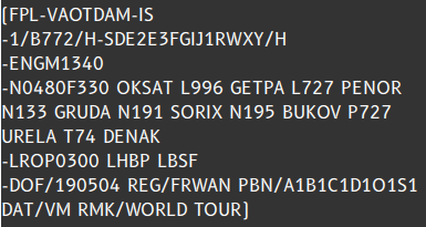
In the example below, the flight plan is checked with your active connection; the callsign used is VAOTDAM and the flight is from ENGM to LROP.

If you click on this area while you have an active flight plan, your flight plan will be displayed in ICAO text format like in the example below:
¶ MTL Selection
When either connected or disconnected, you may change the MTL used without disconnecting by using the MTL button.
When you click on the MTL button, a popup MTL window appears:
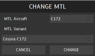
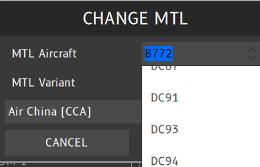
You can select the new MTL Aircraft or MTL Variant in the list provided, or you can type the desired aircraft by using your keyboard also.
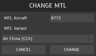
After selection, you have the choice to apply the change by clicking on the CHANGE button or cancel the selection by clicking on the CANCEL button.
If you don't know which MTL to choose. You can take a look at the MTL Catalog and
¶ Pin and Unpin Altitude On Top
At the right of the top area next to the MTL button, you will find the pin icon.
This pin icon can be used to force the UI interface to be in front of all other applications on the screen.
The icon animation is created to make sure that you select the desired configuration:
If the interface is pinned in front of the screen you will see the white icon like the example below:

If the interface is not pinned in front of the screen you will see the grey icon like the example below:

Sometimes the pinning function does not work with some simulator in full screen mode.
¶ Communication Area
The Text Panel displays different types of messages: (see image below):
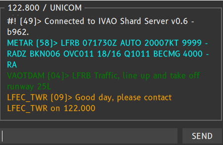
In the example above, you can see:
- Active frequency is 122.800 – the UNICOM frequency
- Message from the IVAO Shard Server v0.6
- METAR request for LFRB airfield (.wx ICAO)
- Sent Message by User (VAOTDAM>)
- ATC (LFEC_TWR) Force Act
The number between brackets [ 00 ] in all messages represents the minute of the hour it's received or sent.
Below you will find all the possible types of messages which can be received by the communication text panel.
¶ Receiving Server Messages
IVAO server system messages from the network (#!>) displayed in white colour just after a successful connection.

If you have tuned your frequency to an ATC station, the selected ATC station and frequency will be displayed instead of the UNICOM channel like the figure above.
In case of Altitude software detects lower framerate when using X-plane that may have a high impact on ATC management or other traffic separation, a specific message is displayed like the one below:
This message is displayed every 20 seconds while ratio is below 70%.

¶ Receiving Messages on Selected Frequency from Other Pilots
Text messages from nearby Pilots are displayed in white colour (the frequency which you are currently tuned to) with their call-sign displayed as a prefix before the message with the “>” separator.
Example: Message sent by AFR88ZW at 18:32 UTC: auto-information message in Unicom

¶ Receiving Messages on Selected Frequency from ATC
Text messages from ATCs sent on the active frequency and directed to you are displayed in green colour (the frequency which you are currently tuned to) with their call-sign displayed as a prefix before the message with the “>” separator.

Text messages from ATC in service on the frequency and not directed to you are displayed in white colour (frequency which you are currently tuned to) with their call-sign displayed as a prefix before the message with the “>” separator.
Example: Message sent by LFRR_CTR at 11:38 UTC: clearance from ATC in current frequency

¶ Sent Messages on Active Frequency
Your own text messages that are sent on the active frequency are displayed with your connected callsign in green.
Example: message sent by VAOTDAM at 15:04 UTC: auto-information message on frequency

Note: your callsign is automatically sent. No need to type it.
¶ ATC Force Act Messages
ATC Force Act is received only for you and sent by an active ATC. The message is displayed in orange.
This message invites you to join/connect the ATC frequency in order to make a controlled flight.
Example: Invitation to contact LFEC_TWR ATC received by the pilot:

ATC invitation to contact is received by using an oceanic SELCAL request paired with dual DTMF tune signals. The message is displayed in orange.
This message invites you to join/connect the ATC frequency in order to make a controlled flight.
Below, you can find an example of SELCAL received by the pilot.

¶ Incoming Private Messages
Incoming private messages are displayed in grey and starts with [MSG] tag.

When you receive a private message, MSG button also blinks red until you open the message window.

¶ Weather Messages
METAR and TAF messages can be received from the network after the server has received a manual request from yourself. Check Dot Commands to see how to request weather information.
The messages are displayed in light blue.

¶ Broadcast Messages
All IVAO Broadcast messages are displayed in red. They are received by all users in the network and these messages can only be sent by IVAO supervisors or administrators.
Example: Broadcast message sent by Supervisor IVAO-MA1 for an ATC exam:

¶ Sending a Message
You may use the field below the Text Panel to send messages. This field could also be used as a scratch pad to take notes. The scratch-pad is followed by a SEND button. When you click on SEND, the entire text written in the scratch-pad is sent on the current frequency.

When sending messages on any frequency, you must use standard phraseology in English having regard to the Self announcing procedure and Phraseology text abbreviation. You may use also the onboard Auto-Unicom module to help you make these announcements on the frequency.
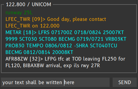
Example: Scratch-pad with the text message ready to be sent on the frequency in: “your text shall be written here”.
¶ Dot Commands
In the scratchpad or in message tabs, you can also send commands. Commands will not be sent on the current frequency as text but commands will be converted by the User Interface as server requests or UI request.
Available commands are:
| Command | Description | Example |
|---|---|---|
| .x <Mode_A_Code> | sets your transponder Mode A code to the specified value | .x 5015 |
| .c1 frequency | sets the COM1 frequency to the chosen frequency in the command | .c1 126.450 |
| .c2 frequency | sets the COM2 frequency to the chosen frequency in the command | .c2 122.000 |
| .metar ICAO .wx ICAO |
Request a METAR of ICAO code airfield (weather information) | .metar LFRS .wx EDDL |
| .taf ICAO | Request a TAF of ICAO code airfield (weather information) | .taf KJFK |
| .wallop Help_Message | Request help in IVAO network from supervisors | .wallop I cannot contact EDDF_APP |
| .chat CALLSIGN | Initiate a private message with a pilot, an ATC, an observer, a supervisor identified by its own Callsign | .chat LEMD_APP |
| .atis ATC_CALLSIGN | get Datalink ATIS from the ATC callsign connected | .atis SBBR_TWR |
| .help | display the onboard command help in the text command window | .help |
Example of METAR command in scratchpad area to be sent by user: (please read article about METAR coding for more information)

Example of a WALLOP call (a wallop call is a message for a supervisor in order to request help)

All commands can be typed on the scratch pad or in any scratch pad of private messages.
¶ Auto-Unicom Module
The button “AU” is the Auto Unicom feature which is a tool for automating UNICOM messages.
It contains a list of predefined messages for each phase of flight.

When the Button is light grey like the example above, this means Auto Unicom Module is not available. You should connect and file a flight plan in order to activate it.
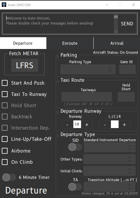
Please consult to the documentation of Auto Unicom Module to learn more!
¶ Transponder Panel
Below the Text panel, there is the Transponder panel (XPDR).
In the transponder panel, you will see the following information:
- 4 digits Mode A Transponder code (named squawk code)
- 2 position Transponder Mode
- Mode STDBY ( standby mode)
- Mode TX (transmission mode which is sometimes TA or TA/RA mode in some aicraft)
- ID button: Starts an IDENT procedure when requested by ATC.
In some regions, transponder should be set to TX mode when taxiing. Always follow ATC instructions in this case.

On initial launch your transponder code will be set to 2000. Your transponder should be set to 2000 when there is no active ATC.

To change the transponder code you may use your aircraft's transponder panel or use chat commands
.x squawk code
Note 2 :If you want more information about transponders, please consult the Transponder Use article.
You should set your transponder mode according to your phase of flight.
- STBY when you are on ground on apron or taxiing.
- TX when you are flying, or taking-off or landing on a runway.
Transponder values are in octal, that means there is no 8 or 9 digit.
¶ Radio Panel
Below the transponder panel, you will find the radio panel.
The radio panel displays your current active COM1 and COM2 frequencies, as well as their associated ATC station names (if available).
The communication channel (COM) status is indicated by the RX/TX button colour:
- A green RX mark indicates which COM channel is currently used to listen to the network frequency programmed on its channel.
- A grey RX mark indicates that the COM channel is in Standby.
- A green TX mark indicates which COM channel is currently used for communication by text and voice to the ATC and/or UNICOM.
- A grey TX mark indicates that the COM channel is on the standby frequency. You will neither be able to transmit on this frequency by text nor by voice.
Example: COM1 and COM2 are set to 122.800 (UNICOM) and COM1 is the active RX and TX channel with the green marks.

¶ CHANGING FREQUENCY ON COM CHANNELS
When connected to the network, left-clicking on a frequency in each COM in the Radio Panel opens the Quick Tune panel. This action allows you to quickly pick a frequency for the selected COM from the list of known nearby ATC stations.
If you left-click on the frequency number, you will open a pop-up menu for automatic tuning by selecting a nearby station:
- If there is no nearby ATC station, you will find only the UNICOM frequency (see bottom left image)
- If there are nearby ATC stations, you will find a selection list where you can choose the desired ATC frequency or UNICOM frequency (see bottom right image)
Example: 2 cases of selection list on COM1 : on the left, a selection list without any ATC (only Unicom available), on the right a selection list with one ATC connected:

The ATC list is sorted by ATC distance with UNICOM as first selection.
It displays only an ATC list in the reception range of your aircraft in function of its position. (you should not have the opportunity to contact New York tower if you are in London!)
When you have selected the wanted ATC position in the list, you left-click on it and the UI will display the new frequency in the selected COM channel with its call-sign displayed just below in white colour.
Note that if the frequency colour is light blue like the example below, that means the active frequency compatible with internal voice module. (If the frequency is not light blue, ATC can be in text mode or have issue with his voice system).
Example1: ATC selected on COM1 is LFRS_APP at 124.425 MHz

Example2: ATC selected on COM2 is LFBB_CTR at 125.105 MHz

If the frequency entered in your cockpit does not match with any active ATC in the reception area of your aircraft, no call-sign will be displayed on the communication area(see example below).
Example: the COM1 frequency is 125.050 and the COM2 frequency is 118.805 and no ATC is detected on this frequency (No call-sign is showed on communication channel). Absolutely nobody will hear your text or voice message if you transmit on this frequency:

In this case, no ATC is connected on this frequency or the station is currently too far from your position.
The ATC list displayed is independent of the communication channel. You will have the same list in COM1 and COM2.
Example: Below you can select when connected on ground at Budapest LHBP the following ATC:
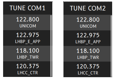
Note that when you have tuned to an ATC station, the Selected ATC station will appear on top of the text panel.

¶ SWITCHING FREQUENCY BETWEEN COM CHANNELS
By clicking on the TX icon on the frequency panel, you can switch from COM1 to COM2 or from COM2 to COM1.
Example: Before changing COM1 to COM2 frequencies, your radio panel may display two different stations like in the example below:
- EDDS_APP selected as primary frequency and active communication channel
- EDDS_TWR selected in standby frequency and stand-by communication channel

By clicking the greyed TX on COM2, you will switch from COM1 to COM2 and you will have this configuration:

You can also change the frequency from your cockpit.
NOTE : Pay attention to the 8.33kHz specific frequencies. Some cockpits inside your simulator are not compatible with these new frequencies. Pay attention that changing frequency by using the UI is mandatory in order to join the adequate ATC. We have implemented a translation module, but it has its limitations.
¶ 2 DIFFERENT SELECTABLE RECEIVING COM CHANNELS
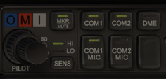
You may have dual RX channels if your simulator and aircraft allows it. You need to click on the second RX button to highlight it in green like in the image below:

NOTE 1 : The second frequency colour (in the example the COM2) is white that means that audio reception is not possible on secondary receiving channel.
NOTE 2 : Dual RX feature is only available for text messages only due to technical limitations. Dual RX voice is not possible today.
Sometimes you may select dual reception inside your cockpit to enable this function.
Example of a secondary text message received on RX only COM (text only mode):

¶ VOICE ACTIVATION AND SETTINGS
¶ RECEIVING AND TRANSMITTING
In Altitude there is an integrated voice module. There is no need to have external voice software anymore in order to speak with active voiced equipped ATC.
In order to speak with an ATC, you shall select one ATC on COM1 or COM2 first. (see above).
When the UI interface is receiving audio transmission, the [RX] button color of the active frequency takes the orange colour.

When the ATC frequency is compatible with audio communication, the colour of the frequency text is light blue like the example above and below.
When the UI interface is transmitting audio transmission, the [TX] button color of the active frequency takes the orange colour. The transmission of audio is driven by the user by pressing the specific Push-To-Talk key programmed in the setting of UI interface (see Setting Tab).

If you press the transmit key for more than 30 seconds, a warning message is displayed on the interface.

When the interface is not receiving or sending audio transmission, both [RX] or [TX] button colour remain dark green in the selected frequency.

¶ SETTING THE VOLUME
The UI interface has a volume adjustment for each of the communication channel COM1 or COM2. The volume can be set by using the round button with a white spot inside.

The volume can be set when you click on the area represented by the "red" spot whenever the volume position is. The hint is displayed
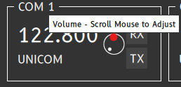
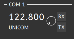
The Volume can be lowered and increased by sliding horizontally the mouse from the click area presented above:
The minimum volume position is :
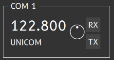
The middle volume position is :
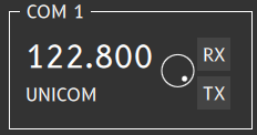
The maximum volume position is :
¶ ACTION BUTTON PANEL
The popup button panel is at the bottom of the UI (User Interface).

You will find the following buttons:
- Connection button
- ATC selection button
- Private message button
- Settings button
- TCAS button
- Datalink ATIS button
- Current UTC hour and online time
¶ CONNECTION BUTTON
When you are not connected, the UI displays the first button with OFFLINE in red.

When you are connected to the IVAO network, the UI will display the first button with ONLINE in green.

¶ CONNECTING TO THE NETWORK AS ACTIVE PILOT
You must click on the OFFLINE button in order to connect to the IVAO network.
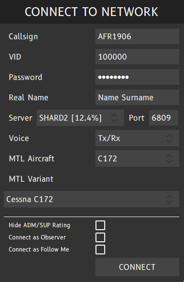
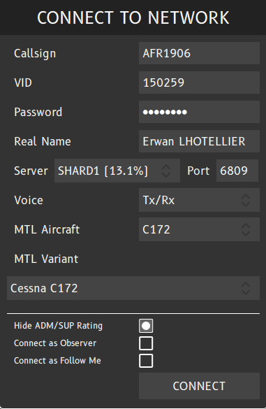
The popup “CONNECT TO NETWORK” appears and you must fill your information in this window:
- Your own callsign for the IVAO network
- Your own VID given by IVAO (example is 100000)
- Your IVAN password given by IVAO
- Your real name (Name + Surname)
- Your selected IVAO server and its port (use default one = 6809)
- Your voice activation plugin
- Your aircraft type presentation for other players connected to the network
- Your airline or texture representation of previous aircraft available in the database for other players connected to the network.
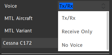
If you want the voice to be actived, you shall select the voice setting:
- Tx/Rx : option that enables the internal voice plugin for voice transmission and reception
- Receive Only : option that enable only the internal voice plugin for voice reception
- No Voice : option that disable the internal voice plugin
There are also 2 options :
- Hide ADM/SUP Rating : only works for supervisors (do not select this option if you are not a supervisor)
- Connect as Observer : only for monitoring the IVAO network or connecting to the network as second pilot for cockpit sharing.
- Connect as Follow Me : only for Follow Me connection on IVAO. Check the IVAO rules and regulation about follow me usage and your division rules. This option is available only to pilot with a certain knowledge.
¶ CONNECTING TO THE NETWORK AS OBSERVER
If you select the observer session with selecting the adequate option button (see image below), you will be considered to observe the IVAO activity near your aircraft location.
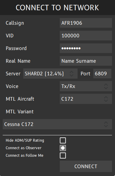
In this situation, pay attention that:
- You can see all nearby traffic (pilots only)
- All IVAO user cannot see your aircraft and your position
- Your connection hours as a Pilot or ATC will be not increasing
- No flight plan is active with your connection.
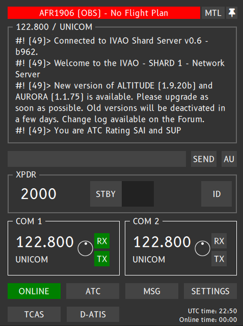
In the image below, you can see after the connected callsign(here AFR1906) the tag (OBS) which indicates you that you are connected as observer. The second tip is when connected as observer the network will send you, your IVAO ATC rating in a message:
¶ CONNECTING TO THE NETWORK AS FOLLOW ME
In order to connect as a follow me, you should fulfill the follow-me rules and regulation of IVAO and also the follow-me rules established by your division.
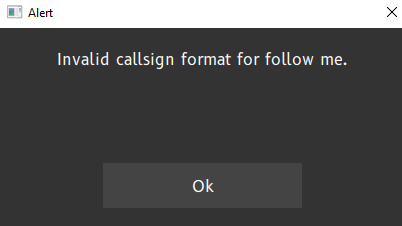
One of these rule is the call-sign format which is ICAOFM00 (the number at the end is the serial number of follow me car of the chosen aerodrome starting with 01).
The MTL aircraft is automatically selected and you can choose one of the possibilities.
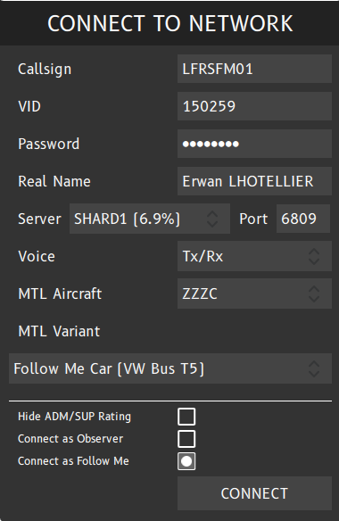
If the callsign does not follow the rules, interface will display this error message:
After connection, your user interface will look something like the image below. You can also see that the user interface recognize you as follow me with the tag [FM]:
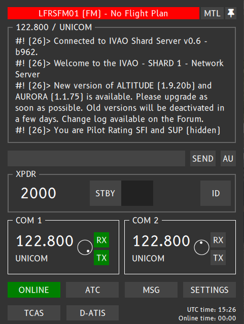
In the example above, you can see that the follow-me callsign is LFRSFM01 with:
- LFRS = Airfied ICAO call-sign (Nantes in France)
- FM = Follow me tag
- 01 = Serial number starting with 01.
¶ DISCONNECTING FROM THE NETWORK
To disconnect from the network, you shall click on the ONLINE green button (see below):

Then a popup window is shown :
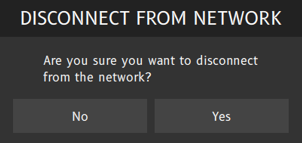
If you click No, you will remain connected to the network.
If you click Yes, you will be disconnected without delay.
¶ CONNECTING COCKPIT SHARING CONNECTION TO IVAO
You must respect the procedure for cockpit sharing flights:
- The first aircraft shall connect to IVAO as a normal flight with the chosen call-sign (Example BAX567)
- The second pilot shall connect as Observer with the same call-sign with one more letter ‘M’ as multiplayer. (Example, BAX567M)
Example of a second aircraft connection with BAX567M:
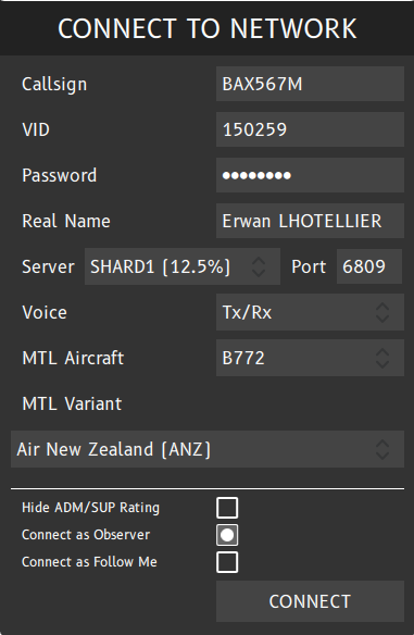
With that specific connection, the MTL/CSL of the main connection is hidden.
Pay attention that the second pilot connection is considered as observer in the IVAO network. His connection hours will not be increased and his connection is never seen by ATC.
¶ ATC POPUP
When you are online and connected to the IVAO Network, you will have the following menu:

When your are ONLINE, if you click on the ATC button, the ATC popup window opens with the “NEARBY ATC STATIONS” title:
- If there is no ATC station nearby your position, you will find only the UNICOM channel on this popup like the first image on the bottom left.
- If there are ATC stations nearby your position, you will find the UNICOM channel, and all ATC channels listed below sorted by distance like the second image on the bottom right.
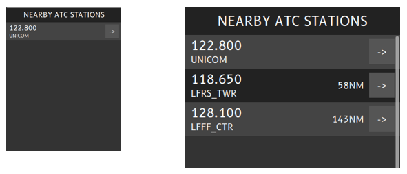
Note: If you are not online (offline), you will never see any ATC.
When you select an active ATC in the list, you can choose one of the following actions:
- initiate a private chat by clicking on MESSAGES
- set ATC frequency to COM1 by clicking TUNE COM1
- set ATC frequency to COM2 by clicking TUNE COM2
- get ATC ATIS by selecting the REQ. ATIS
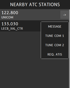
See Datalink-ATIS area for the output result of the REQ ATIS command.
If you want to know more about the ATC position responsibilities, please read the Air traffic control position documentation.
¶ Private Message Window (Chat)
When you click on the MSG button, you will open the private message popup window.

This messages popup window allows you to visualize and exchange private messages with other members of the network.
Each time you receive a new private message, a specific sound is played and the MSG button is blinking in red, in order to indicate that you have received new message(s):

When you click on the MSG button, it will display the channel of the last private message received automatically (in my example IVAO-DM1):
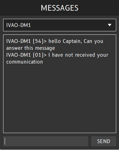
The drop-down panel of the message popup window lists all your current private conversations, and allows to select one for reading and/or sending messages to that conversation.
If you click on the white triangle or inside the selection bar, you will display a list of open channels with you (see image below):
- each line will correspond to one private chat or communication channel
- the communication channel can be established with an active pilot, an active ATC, an observer or an IVAO staff member who are connected to the network.
- the 'X' sign in front of each callsign is the closing communication switch (meaning that if you press the 'X', you will lose all the history of the chat).
- the dot sign in front of each callsign represents the activity of the channel. If the dot colour is light blue, it means that this channel has received one new communication that you have not read yet.
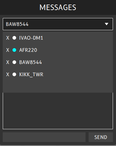
On the example above, we have a chat open with:
- IVAO-DM1 (Observer Staff) (callsign starting with IVAO are HQ IVAO staff people)
- AFR220 (Pilot) (channel has a non read message received and is ready to be read)
- BAW8549 (Pilot)
- KIKK_TWR (ATC)
In order to select one specific channel, just click on the desired callsign to communicate with, then it opens the chat window with this specific callsign.

NOTE 1 : You can initiate a new chat manually by using the dot .CHAT command in the Scratchpad of the Text panel.
NOTE 2: All private messages will follow the same rules as those for the text panel (prefix usage).
NOTE 3 : When receiving an incoming message, the UI interface will switch automatically to the incoming message channel after pressing the MSG button.
¶ SETTINGS POPUP WINDOW
The settings popup window is the area to set up your User Interface for specific actions, display or configuration.
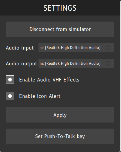
The UI settings will offer you the available options:
- Force disconnection button : disconnects the PilotUI from the simulator, if no other PilotUI is running on a different machine, this will also result in a disconnect from the network.
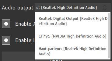
- Audio input hardware setting : left-click on right area where hardware by default is shown and select the wanted one.
- Audio output hardware setting : left-click on right area where hardware by default is shown and select the wanted one.
- Enable Audio VHF effect option : left-click on button to enable or disable the VHF effect like microphone clicks, VHF background noise, frequency blocking effect ...
- Enable Icon Alert : left-click on button to enable or disable the blink effect on the pilot client task bar icon.
- Apply button to save the changes into the settings for next PilotUI launch
- Set Push-To-Talk Key option : Click on the button then press the new PTT(Push-To-Talk) key for voice transmission (We advise to select silent key like CTRL, SHIFT or ALT keys).
The default PTT key is the left [CTRL] key on your keyboard :
¶ TCAS BUTTON
When pressing the TCAS button, the TCAS window popup will appear.
The TCAS is the onboard Traffic Collision Avoidance System provided by the UI interface.
Example: By default the TCAS system is disabled (STBY mode):
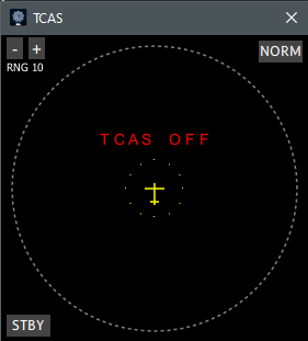
The TCAS modes, selected on the bottom left, are:
- Standby mode - STBY ( TCAS is deactivated )
- Traffic Advisory mode - TA ( This mode alerts the pilot through a collision alert sound only )
- Traffic Advisory and Resolution Advisory mode - TA/RA ( This mode alerts the pilot through collision information and gives resolution clearances that the pilot shall comply with without delay)
Example: After clicking on the STBY button, the TCAS system is set to the TA mode:
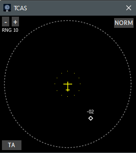
Example: After clicking on the TA button, the TCAS system is set to the TA/RA mode:
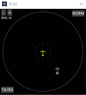
Note in both images above, traffic is displayed at -200ft from your vertical position (relative altitude)
There are 2 button for display configuration for this TCAS:
- Top left button = Horizontal Visibility Range : Available ranges are 3NM, 5NM, 10NM, 15NM, 20NM or 40NM
- Top Right Button = Vertical Visibility Range : Available ranges are NORM, ABV, BLW , ALL
The Vertical Visibility Range definition is:
- NORM: traffic at +/- 2700 ft is displayed
- ALL: all traffic within the TCAS range is displayed
- ABV: traffic within the interval (-2700, +9000) ft is displayed
- BLW: traffic within the interval (-9000, +2700) ft is displayed
There is one sound mute function available for TCAS by using the bottom right button.
¶ DATALINK ATIS
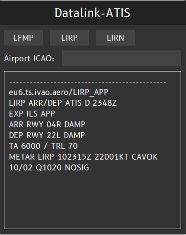
When pressing the D-ATIS button, a new window opens the Datalink ATIS (automatic terminal information service ) feature to manage ATIS messages like in some aircraft systems.
Note : At IVAO we only have text ATIS for the moment, as voiced ATIS is not implemented and ATIS is not associated by a separate frequency today. So the IVAO pilot software implements the Datalink ATIS for all aircraft.
After you pressed the D-ATIS button, the Datalink ATIS window is displayed like the image below, which represents the Datalink ATIS when you do not have any active flight plan or you are disconnected.
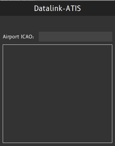
After you have been connected to the IVAO server, and the flight plan was correlated with your callsign and flight plan server, the Datalink ATIS will show the windows like in the example below:
Note: At the top, you may find 2 to 4 ICAO airfield codes from your flight plan:
- First airfield is the departure airfield
- Second airfield is the arrival airfield
- Third airfield is the first alternate airfield
- Fourth airfield is the second alternate airfield
Example: flight plan OJAI to OBBI with 2 alternate airfields OEDF and OTHH:
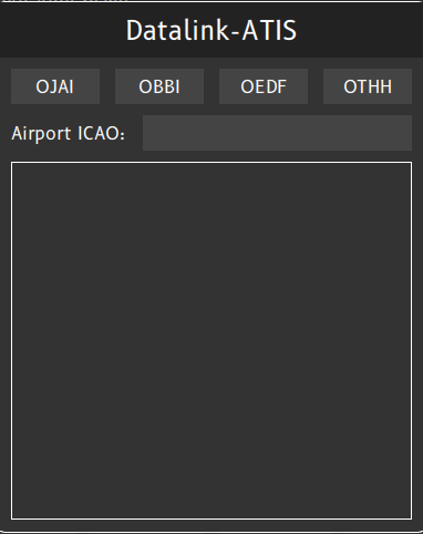
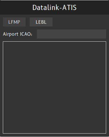
Example: A flight plan LFMP to LEBL without alternate airfields declared:
If you click on one of the departure, arrival or alternate ICAO codes, there are 2 cases:
- Case 1: If there is no ATC connected on this selected airfield, then it displays an empty ATC list.
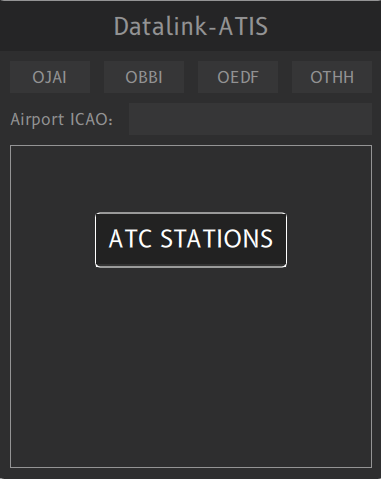
Then you cannot request any ATIS from this ICAO airfield. You should check for another ATC position which can take your departure, or start your flight by using auto-information on UNICOM if there is no other ATC station (check METAR for weather information).
- Case 2: There are one or several ATC stations connected on this selected airfield, then it displays an ATC station list and you can choose the desired ATC from the list displayed:
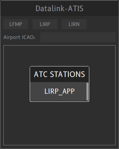
After selecting the chosen ATC in the list, the Datalink ATIS will display the ATIS information:
Note that the ATIS of each station is displayed after a separation line "---------------------".
In order to get one ATIS from any desired ATC station, you should write in the scratch-pad area of the Airport ICAO, the desired ATC position:
- Step 1: You want to request any ATC connected on SBXS:
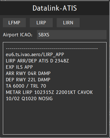
- Step 2: After ICAO code validation, the UI will display the ATC list available on this position (here is one ATC station only = SBXS_APP):
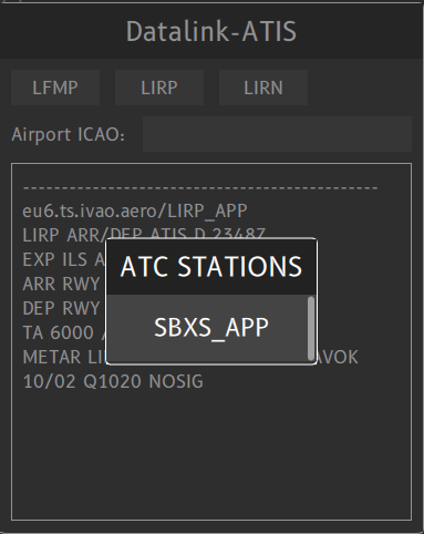
- Step 3 : After selecting the SBXS_APP position, the UI will display the SBXS_APP ATIS after the separator line.
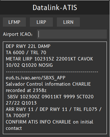
NOTE : You can browse all the Datalink ATIS data with your mouse central wheel.
If you type the dot command .ATIS on the main frequency scratch-pad, the ATIS will be displayed in the Datalink ATIS area.
After command validation, the D-ATIS button is blinking if there is any output available. The button is blinking until you click and select the D-ATIS window.

After clicking the D-ATIS button, you can read your desired ATIS (see example SBXS_APP).
If there is no ATC station connected on this position, D-ATIS will not blink and there is no input.
¶ UTC AND CONNECTION TIME
On bottom right of the UI interface, you will find:
the current UTC time whic is the official hour to use in the flight plan, flight report in IVAO
the number of hours and minutes counter which compute your connected time online. This counter is displayed only if you are connected on IVAO
Example: UTC time is 15H38 and your online time is 3 minutes.

¶ SIMULATOR PLUGIN SETTINGS
¶ COMMUNICATION TEXT DISPLAYED INSIDE THE SIMULATOR
The messages received on your main frequency, all the private messages and system messages are also received inside your flight simulator.
- If you fly FSX / P3D, the messages are displayed with a green bar by default.
- If you fly X-plane, the messages will be displayed in a transparent window which must be activated first through the following process
Open X-Plane and launch a flight, on the top menu bar click on "Plugins" then "IVAO Pilot Client"
Activate the window by clicking on "Toggle message window" Verify that a white dot is displayed before the selection (in the image

Verify that the window is displayed :

There is another option witch is The toggle alert window :
The toggle alert window will open when receiving some alert like the force act and displayed in yellow

- yellow = Contact ATC message
- green = ATC text message to me
- red = broadcast
- grey = wallop, PM
- white = default
¶ AIRCRAFT TAGGING
The tagging setting is the option that drives the aircraft callsign above or below the MTL / CSL. This setting is not real but it can help to communicate with pilots on the UNICOM frequency.
X-Plane :
- Open X-Plane and launch a flight, on the top menu bar click on "Plugins" then "IVAO Pilot Client"
- Activate the window by clicking on "Toggle plane label"

FSX :
- Go to Settings -> Multiplayer -> Aircraft tagging
¶ CUSTOMIZE THE UI SOUNDS
To customize UI Sounds, put a new .wav file with following name in the subdirectory \sounds where PilotUI.exe is located:
- connect.wav: connected sound
- disconnect.wav: disconnected sound
- freq.wav: incoming frequency message
- freqme.wav: incoming frequency message directed to me
- private.wav: private messsage
- wallop.wav: wallop
- forceact.wav: force ATC notice
- broadcast.wav: broadcast sound
Note 1 : If you want to deactivate one sound (example: incoming message on frequency not for me), with you notepas just create an empty text file and rename or save it as the chosen name above (example: freq.wav)
Note 2 : The sounds sample rate shall be set maximum to 24bit. Altitude is not compatible with 32bit sample rate.
¶ Parameter File
There is one parameter file which is located in main simulator directory:
The file is : IVAO_Pilot_Client.conf
[GENERAL]
AIRCRAFTLABEL=1
DISPLAYSIMMESSAGE=0
MTLVISIBILITYRANGE=50
The available parameter are :
- AIRCRAFTLABEL : to display or not the label of aircraft (1=ON; 0=OFF)
- DISPLAYSIMMESSAGE : to display or not the message from Altitude in the simulator (1=ON; 0=OFF)
- MTLVISIBILITYRANGE : set the distance to display the MTL or CSL : 5 NM < value < 50 NM
¶ Supervisor Commands
Supervisor commands are implemented in the IVAO Pilot software.
- All wallop messages will be received in a separate private chat named [WALLOP] (see below).
- Each new incoming wallop message will produce a specific sound, different from private messages.
- Every message written in this specific WALLOP tab will automatically send wallops without typing the specific command .wallop
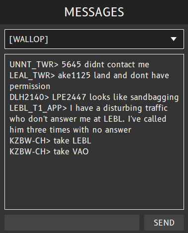
Here is the list of available commands for supervisors:
| Command | Description |
| .info | Request connection information from a member connected as Callsign |
| .kill | Kill a member connected as Callsign with a reason inserted (reason is mandatory) |
| .broad | Send a broadcast message to all members |
| .wallop | Send to other supervisors a message for chatting to all supervisors or acknowledge a wallop. |
Warning: If you type the .kill command without inserting a reason, an error popup is displayed:
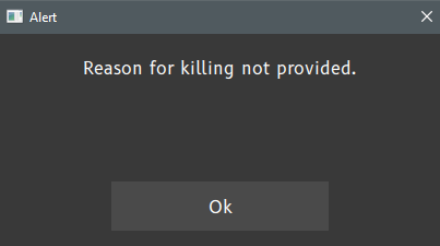
The option Hide SUP/ADMIN Rating is available in the connection window in order to show you as Supervisor online in Webeye.
¶ AUTHOR
- VID 150259 - Creation
- VID 150259 - Updates 12-10-2020
- VID 573229 - Updates
¶ COPYRIGHT
- This documentation is copyrighted as part of the intellectual property of the International Virtual Aviation Organisation.
¶ DISCLAIMER
- The content of this documentation is intended for aviation simulation only and must not be used for real aviation operations.
